Method and device for operating a drive device, and drive device

A technology for driving equipment and equipment, which is applied to the arrangement of multiple prime movers, mechanical equipment, transportation and packaging of general power plants, and can solve the problems of loss of comfort and lack of flexibility, and achieve the goal of increasing boost pressure Effect

Inactive Publication Date: 2018-06-08
ROBERT BOSCH GMBH
View PDF9 Cites 0 Cited by
  • Summary
  • Abstract
  • Description
  • Claims
  • Application Information

AI Technical Summary

Problems solved by technology

In the event of a sudden increase in the target torque and in the event of a change in the power of one or both exhaust turbochargers, this delay leads to a loss of comfort during driving operation, especially a loss of agility

Method used


Image

  • Method and device for operating a drive device, and drive device
  • Method and device for operating a drive device, and drive device
  • Method and device for operating a drive device, and drive device

Examples


Embodiment Construction

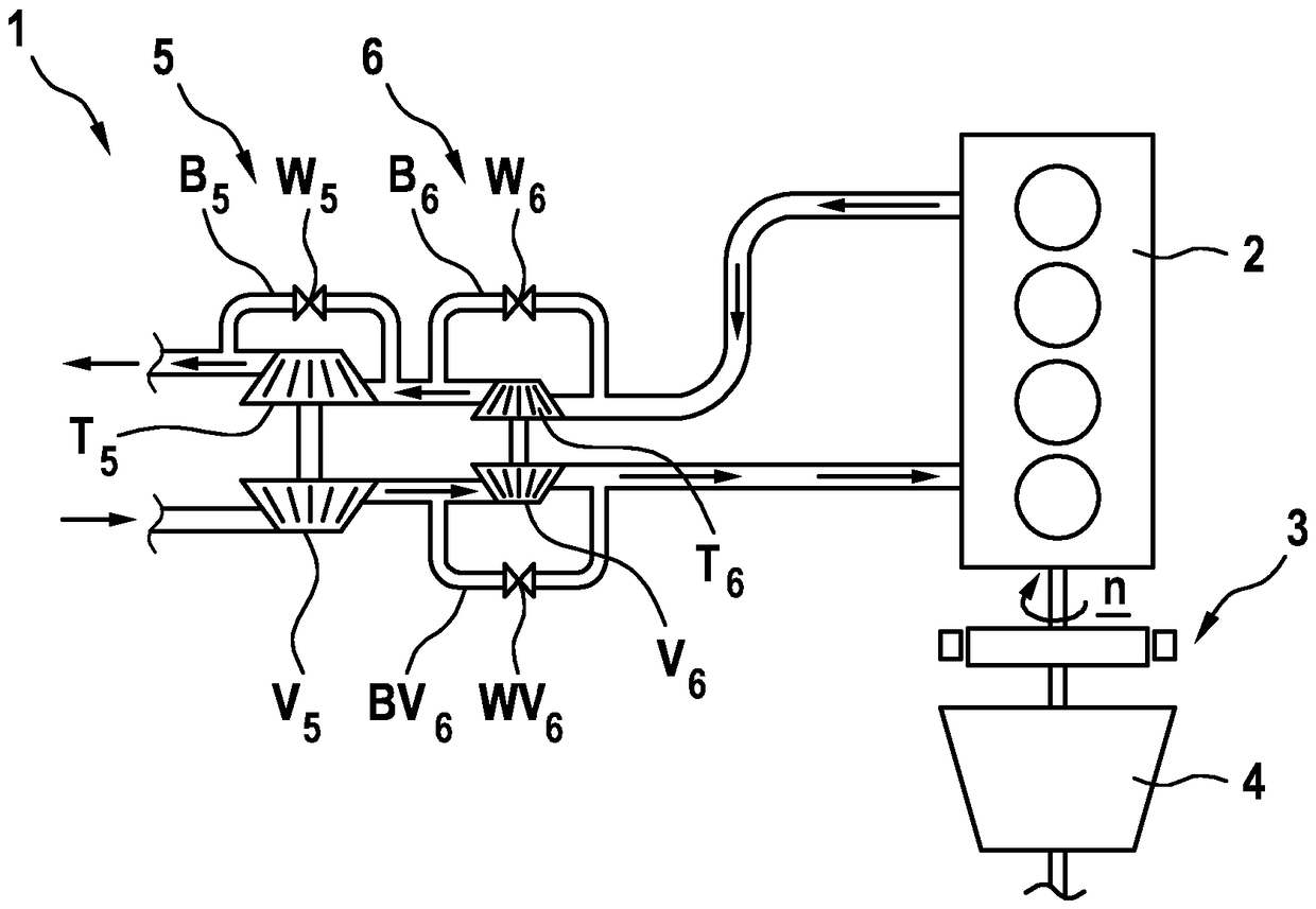
[0021] figure 1 The drive unit 1 of the motor vehicle, which is not shown in detail here, is shown in a simplified illustration. The drive device 1 has a combustion motor 2 which is designed as a traction piston motor. The combustion motor 2 or the crankshaft of the combustion motor 2 is connected to the electric machine 3 . The rotor of the electric machine 3 is arranged in a rotationally fixed manner directly on the crankshaft 2 or on the output shaft of the combustion motor 2 . The electric machine 3 is in turn connected to a transmission 4 , which connects the drive unit 1 to the drive wheels of the motor vehicle. The transmission 4 here has in particular a plurality of gear stages, between which gear stages can be changed.

[0022] The combustion engine 2 is assigned two exhaust gas turbochargers 5 and 6 which are connected in series. The two exhaust gas turbochargers 5 , 6 each have a turbine T 5 , T 6 and the compressor V connected to the turbine 5 and V 6 . Th...


PUM


Abstract

The invention relates to a method for operating a drive device (1) of a motor vehicle, comprising an internal combustion engine (2) having a first exhaust gas turbocharger (5) and a second exhaust gasturbocharger (6), and comprising at least one electric machine (3), wherein the exhaust gas turbochargers (5, 6) are connected in series, wherein at least the second exhaust gas turbocharger (6) hasmeans for varying the output thereof, and wherein the output at least of the second exhaust gas turbocharger (6) is varied in accordance with a required target torque of the drive device (1). According to the invention, the electric machine (3) is controlled in accordance with the time of the variation, in order to compensate for a deviation of an actual torque of the drive device (1) from the target torque.

Description

technical field [0001] The invention relates to a method for operating a drive system of a motor vehicle having a combustion motor with a first exhaust gas turbocharger and a second exhaust gas turbocharger and at least one electric machine, wherein the exhaust gas turbocharger The compressors are connected in series, wherein at least the second exhaust gas turbocharger has means for modifying its power, wherein the power of at least the second exhaust gas turbocharger is modified according to the required target torque of the drive machine. [0002] Furthermore, the invention relates to a device for operating the above-described drive device and a corresponding drive device. Background technique [0003] Methods, devices and drive devices of the type mentioned at the outset are known from the prior art. In order to increase the performance of combustion motors, it is known to assign an exhaust gas turbocharger to the combustion motor, which is driven by the exhaust gas of ...

Claims


Application Information

Patent Timeline
Patent Type & Authority Applications(China)
IPC IPC(8): F02D41/00B60W10/06B60W10/08F02B37/12
CPCB60W10/06B60W10/08B60W2510/0633B60W2510/083B60Y2400/435B60W20/19F02B37/004F02B37/013F02B37/12F02B37/16F02B37/18F02B37/24F02D41/0007F02D2200/1002F02D2250/18Y02T10/12Y02T10/62B60K6/48B60W2540/10B60W2710/0638B60W2710/0666B60W2710/083B60Y2200/92B60W20/15
Inventor B.马特罗斯D.巴罗伊特K.泰斯
Owner ROBERT BOSCH GMBH
Why Eureka
Try Eureka