Method for controlling a valve and corresponding valve apparatus

A technology for controlling valve and valve position, applied in valve device, valve operation/release device, fluid pressure actuating device, etc., can solve the problems of mechanical failure downtime, hidden safety hazards, etc., and achieve the effect of reducing damage

Active Publication Date: 2018-06-08
WOODWARD GOVERNOR CO
View PDF3 Cites 0 Cited by
  • Summary
  • Abstract
  • Description
  • Claims
  • Application Information

AI Technical Summary

Problems solved by technology

Under similar circumstances, the shock absorber may provide a longer service life than a valve without the shock absorber, but the shock absorber is still considered a consumable part because of the repeatability between the valve and the shock absorber. High-velocity impacts still result in cumulative damage that can result in mechanical failure, downtime for repairs, or safety hazards

Method used


Image

  • Method for controlling a valve and corresponding valve apparatus
  • Method for controlling a valve and corresponding valve apparatus
  • Method for controlling a valve and corresponding valve apparatus

Examples


Embodiment Construction

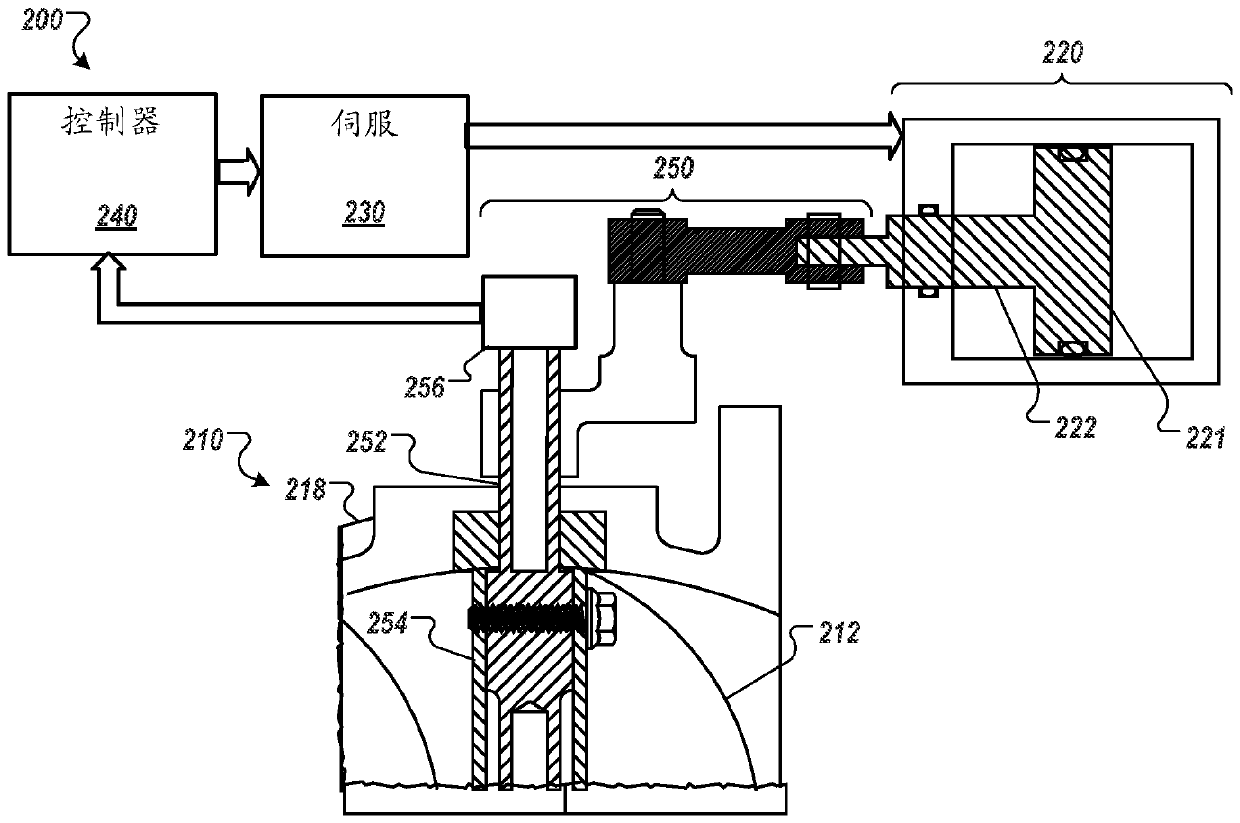
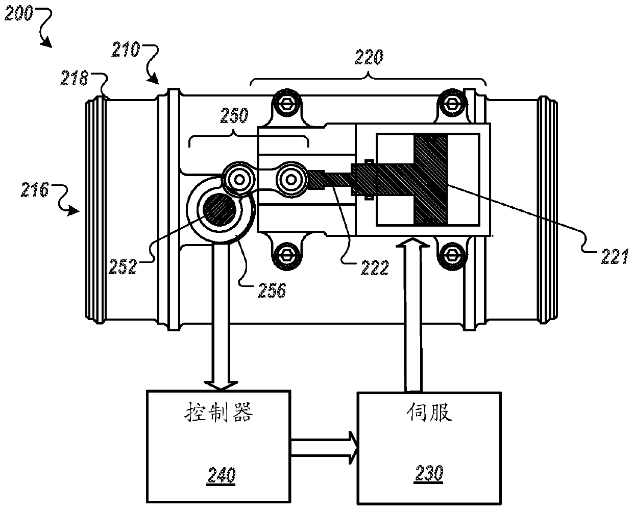
[0020] This document describes systems and techniques for controlling fluid flow using valves with variable stroke rates. Steam turbine valves are subject to small but cumulatively significant damage when the valve closes rapidly, such as during a shutdown. This makes the ability to rate limit the valve in the travel region near the valve seat highly desirable. The solution to this problem is complicated by the fact that the linkage to the steam turbine valve can grow or shrink significantly with temperature, so that the actual position of the valve seat is unknown to the control. As used herein, the term "valve seat" means the surface that the valve contacts to shut off the flow of fluid through the valve when the valve is closed. For example, on a poppet-style valve, the sealing surfaces must be tightly pressed against each other firmly, so they also act as a hard stop. If the sealing surfaces of the valves are damaged by impact, they may no longer seal well. Another comp...


PUM


Abstract

The subject matter of this specification can be embodied in, among other things, a method for controlling a valve includes providing a valve having an actuator configured to move a valve member between an open valve position and a closed valve position, moving by the actuator and at a first valve closure rate the valve member away from the open valve position and toward a threshold valve positionaway from the closed valve position, and moving by the actuator and at a second valve closure rate the valve member from the threshold valve position toward the closed valve position. A correspondingvalve apparatus is also provided.

Description

technical field [0001] This specification relates to valves with variable closing rate limitation. Background technique [0002] Some type of cushioning is usually required to decelerate the valve before it hits the valve seat. Cushioning of the valve as it approaches the seat reduces stress on the valve components and reduces vibrations transmitted to the machine structure. Seat shock is generally handled in three ways: through simple shock cushioning, fluid cushioning, or by installing shock absorbers. Fluid cushioning typically involves the use of spring-loaded check valves to divert pressure spikes around the valve. Dampers typically introduce a degree of mechanical compliance between the valve and seat. Fluid dampers and shock absorbers add to the mechanical complexity of the valve and can be prone to leaks, especially when the pressure of the fluid being regulated is similar to that of the fluid triggering the damper mechanism. [0003] Hydraulic dampers that restr...

Claims


Application Information

Patent Timeline
Patent Type & Authority Applications(China)
IPC IPC(8): F01D17/14F15B11/048
CPCF01D5/189F01D9/041F01D17/145F05D2240/12F05D2250/90F05D2260/201F15B11/048F15B2211/6336F15B2211/75F15B2211/853F15B2211/8606F16K1/2007F16K31/122F16K31/521F16K37/0041
Inventor R.L.坎普豪斯G.A.莫伦纳尔T.K.布里特
Owner WOODWARD GOVERNOR CO
Why Eureka
Try Eureka