
Aircraft cabin air temperature sensing apparatus and system using passive air flow

A technology of air flow and temperature sensing, applied in the temperature measurement of moving fluid, temperature measurement in air conditioning system, air conditioning system, etc., can solve problems such as no solution

Inactive Publication Date: 2018-06-08
BOMBARDIER INC
View PDF7 Cites 0 Cited by
  • Summary
  • Abstract
  • Description
  • Claims
  • Application Information

AI Technical Summary

Problems solved by technology

However, there is currently no solution for temperature sensing devices known in the prior art
[0013] Simply put, existing technology does not provide a suitable solution to one or more of the difficulties enumerated above

Method used


Image

  • Aircraft cabin air temperature sensing apparatus and system using passive air flow
  • Aircraft cabin air temperature sensing apparatus and system using passive air flow
  • Aircraft cabin air temperature sensing apparatus and system using passive air flow

Examples


Embodiment Construction

[0058] The invention will now be described in conjunction with one or more embodiments of the invention. The discussion of various embodiments is not intended to limit the invention. Rather, any discussion of various embodiments is intended to illustrate the breadth and scope of the invention. It will be apparent to those skilled in the art that variations and equivalents of the embodiment(s) described herein may be employed without departing from the scope of the invention. These modifications and equivalents are intended to be included within the scope of this patent application.

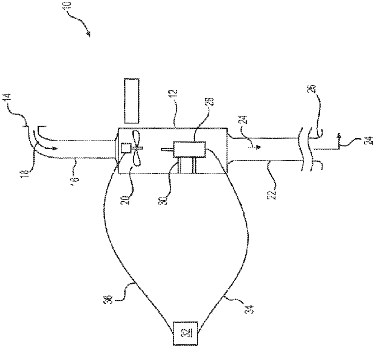
[0059] FIG. 1 is a diagrammatic view of a portion of an air duct assembly mount 10 in an aircraft showing a conventional temperature sensing device 12 according to the prior art. The air duct assembly mount 10 includes an inlet 14 that draws air from the cabin or cockpit of the aircraft into an inlet portion 16 of the air duct assembly mount 10 . In the following discussion, the air flowing int...


PUM


Abstract

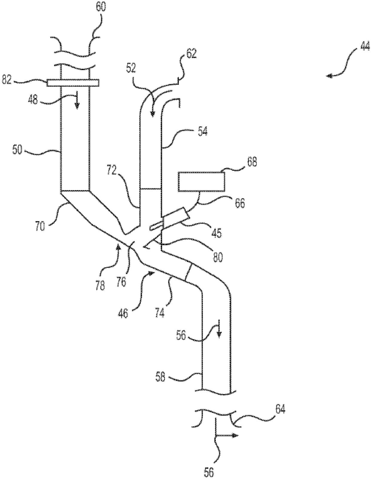
An air temperature sensing apparatus and a system for an aircraft include an ejector with a first air duct (118) for receiving a first air flow (120) from an aircraft air distribution duct, the firstair duct (118) defining a first cross-sectional area (134), a second air duct (122) for receiving a second air flow (124) from a passenger compartment of the aircraft, the second air flow (124) merging with the first air flow (120) downstream of the second air duct (122), and a restrictor (130) connected to the first air duct (118) defining a minimal cross-sectional area (144). The apparatus and system also include a temperature sensor (140) in fluid communication with the second air flow (124). The minimal cross-sectional area (144) of the restrictor is smaller than the first cross-sectionalarea (134) of the first air duct to create a region of low pressure within the ejector, causing the second air flow (124) to be suctioned over the temperature sensor (140).

Description

[0001] Cross References to Related Applications [0002] This patent application relies on the priority of US Provisional Patent Application Serial No. 62 / 239,002, filed October 8, 2015, which is incorporated herein by reference in its entirety. field of invention [0003] The present invention relates to devices and systems for sensing the temperature of the air in an aircraft cabin. More specifically, the present invention relates to the construction of air duct assemblies for use in aircraft that utilize passive air flow through the ducts to facilitate accurate cabin air temperature measurements. A system is also provided. Background technique [0004] It is obvious to those skilled in the art of aircraft manufacturing that it is desirable to maintain the temperature of the air in the cabin of an aircraft within certain limits for the comfort of the passengers and crew. [0005] Air temperature within an aircraft cabin is typically measured by one or more temperature s...

Claims


Application Information

Patent Timeline
Patent Type & Authority Applications(China)
IPC IPC(8): B64D13/00B64D13/06
CPCB64D13/00B64D2013/0625Y02T50/40G01K13/024B64D13/06G01K1/26G01K13/02G01K2201/02
Inventor 桑德罗·阿丰索·席尔瓦·法贡德斯卢恰诺·马丁内斯·斯特凡尼尼王宏志
Owner BOMBARDIER INC
Learn More