
Electric vehicle control device, electric vehicle control system, and electric vehicle control method

An electric vehicle and control device technology, which is applied in the direction of road vehicle drive control system, control device, ASR control system, etc., can solve problems such as inability to accurately suppress vibration, signal without sign, and inability to identify rotation direction.

Inactive Publication Date: 2018-06-08
HITACHI AUTOMOTIVE SYST LTD
View PDF6 Cites 5 Cited by
  • Summary
  • Abstract
  • Description
  • Claims
  • Application Information

AI Technical Summary

Problems solved by technology

[0007] However, in general, the signal of the wheel speed sensor has no sign, and the direction of rotation cannot be recognized, so there is a problem that the vibration cannot be accurately suppressed when the vehicle is moving backwards, and a sufficient vibration suppression effect cannot be obtained

Method used


Image

  • Electric vehicle control device, electric vehicle control system, and electric vehicle control method
  • Electric vehicle control device, electric vehicle control system, and electric vehicle control method
  • Electric vehicle control device, electric vehicle control system, and electric vehicle control method

Examples


Embodiment 1

[0020] figure 1 It is a system diagram of the electric vehicle of the first embodiment. The electric vehicle of the first embodiment is a front-wheel drive vehicle (two-wheel drive vehicle) in which the front wheels FL and FR are driven by an electric motor 1. The differential gear 3 is connected to the electric motor 1 via the reduction mechanism 2. A drive shaft 4 is connected to the differential gear 3. Front wheels FL and FR are connected to the drive shaft 4. Electric power is supplied to the electric motor 1 via an inverter 5 from a high-voltage battery (not shown). The driving of the inverter 5 is controlled by the vehicle controller 6.

[0021] The electric vehicle has a shift lever 12 that outputs a gear signal indicating the driving mode of the vehicle, an accelerator opening sensor 7 that outputs an accelerator opening signal, and a resolver 8 that outputs a motor rotation speed signal including the rotation direction of the electric motor 1. The vehicle controller...


PUM


Abstract

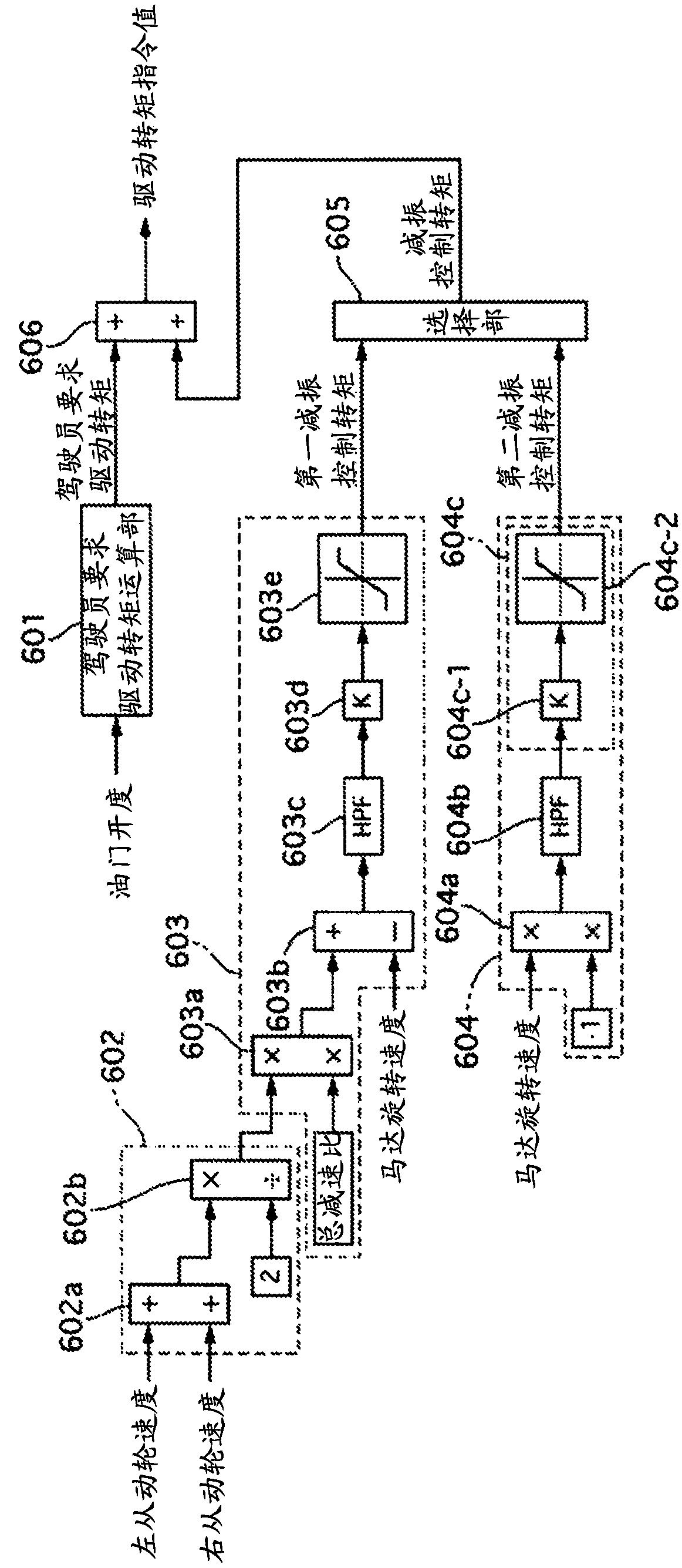
The purpose of the present invention is to provide an electric vehicle control device capable of obtaining a vibration suppression effect regardless of the wheel rotation direction. A first vibration-dampening control torque and a second vibration-dampening control torque are selectively output in one embodiment of the present invention, said first vibration-dampening control torque being calculated by using a first calculation method on the basis of a wheel speed sensor signal during forward travel of the electric vehicle and said second vibration-dampening control torque being calculated byusing a second calculation method different from the first calculation method, during reverse travel of the electric vehicle.

Description

Technical field [0001] The invention relates to a control device, a control system and a control method of an electric vehicle. Background technique [0002] In the conventional electric vehicle control device, the difference between the motor rotation speed and the average rotation speed of the left and right drive wheels is extracted as the vibration component of the torque vibration of the torque transmission system, and the vibration reduction for canceling the vibration component is calculated Control the torque and correct the driver's required drive torque. Patent Document 1 describes an example related to the technique described above. [0003] Prior art literature [0004] Patent literature [0005] Patent Document 1: Japanese Patent Application Publication No. 2002-152916 Summary of the invention [0006] The technical problem to be solved by the invention [0007] However, the signal of the general wheel speed sensor has no sign and cannot recognize the direction of rotati...

Claims


Application Information

Patent Timeline
Patent Type & Authority Applications(China)
IPC IPC(8): B60L15/20B60L9/18
CPCB60L3/106B60L15/10B60L2240/486B60L2260/26B60T2270/20B60Y2300/18033B60Y2300/18175B60L2240/12B60L2240/16B60L2240/32B60L2240/421B60L2240/461B60L15/20B60L2270/145B60W30/20B60W2520/06B60W2520/28Y02T10/64Y02T10/72B60L2220/46B60L2240/423
Inventor 铃木圭介金子聪
Owner HITACHI AUTOMOTIVE SYST LTD
Learn More