Method and device for producing a metal strip with substantially parallel strip edges

A metal belt and belt edge technology, used in metal processing equipment, manufacturing tools, shearing machine equipment, etc., can solve the problem of the required size of the bandwidth and the deviation of the belt edge, and achieve the effect of avoiding offset and small structure space.

Active Publication Date: 2018-06-08
BERNDORF BAND GMBH
View PDF6 Cites 0 Cited by
  • Summary
  • Abstract
  • Description
  • Claims
  • Application Information

AI Technical Summary

Problems solved by technology

In addition, bows in the metal strip can also lead to failure to maintain the required dimensions of the band or to deviate from the parallel profile of the strip edges, in particular if the bows are pressed in the region of the processing point, for example by roller pairs. when together

Method used


Image

  • Method and device for producing a metal strip with substantially parallel strip edges
  • Method and device for producing a metal strip with substantially parallel strip edges
  • Method and device for producing a metal strip with substantially parallel strip edges

Examples


Embodiment Construction

[0074] First of all, it should be confirmed that in the differently described embodiments, the same parts have the same reference signs or the same component designations, wherein the disclosure content contained in the entire description can be transferred to the same figure with the same figure Mark or on the same part of the same component name. Furthermore, selected positional descriptions in the description, such as top, bottom, side, etc., refer to the currently described or illustrated drawing and can be transferred to a new position in the event of a change of position. Furthermore, individual features or combinations of features from the various exemplary embodiments shown and described constitute independent, inventive or inventive solutions in themselves.

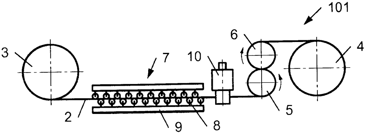
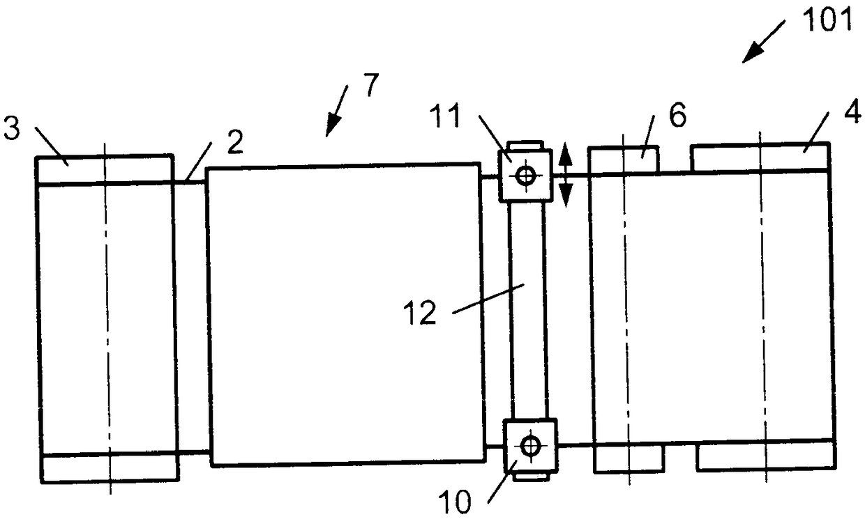
[0075] figure 1 and figure 2 shows an arrangement system 101 for producing a metal strip 2 with substantially parallel strip edges, figure 1 is the side view, figure 2is a top view. The deployment system 1...


PUM


Abstract

The invention relates to a method for producing a metal strip (2) with substantially parallel strip edges (20, 21), in which the metal strip (2) is edged, in that at least a part of the strip edges (20, 21) of the metal strip (2) is removed. In addition, the metal strip (2) is plastically reshaped during a straightening process. In order to carry out the method, a device (101...106) is provided, which comprises a trimming tool (10, 11) and a drive (3...6, 15...18) for generating a relative movement between the trimming tool (10, 11) and the metal strip (2) in the direction of the longitudinalaxis of the metal strip (2). The device (101...106) also comprises a unit (7, 22...25) for plastic reshaping of the metal strip (2).

Description

technical field [0001] The invention relates to a method for producing a metal strip with substantially parallel strip edges, wherein the metal strip is trimmed by removing at least a portion of the strip edge of the metal strip. Furthermore, the invention relates to a device for trimming a metal strip, said device comprising a trimming tool and a drive for generating a relative movement between the trimming tool and the metal strip in the direction of the longitudinal axis of the metal strip device. Background technique [0002] The metal strip is produced for a specific use with a very high surface quality and is also ground or polished in this way after trimming. Such metal strips are used, for example, for the production of plate-like or film-like materials, in particular for photographic films, LCD screens or also for artificial stone (“Engineered Stone”) and for the production of wooden materials ( such as particleboard, laminate or similar). Here, a liquid or pasty...

Claims


Application Information

Patent Timeline
Patent Type & Authority Applications(China)
IPC IPC(8): B21D1/02B21D1/05
CPCB21B1/22B21D1/02B23D19/06B21D1/05
Inventor R·舒斯特
Owner BERNDORF BAND GMBH
Why Eureka
Try Eureka