Aerosol-generating system with self-activated electric heater

An aerosol generation and electric heater technology, which can be used in inhalers, tobacco, tobacco processing, etc., can solve the problems of adverse effects on the accuracy of consumption, and the consumption is not estimated accurately enough.

Active Publication Date: 2018-06-08
PHILIP MORRIS PROD SA
View PDF4 Cites 6 Cited by
  • Summary
  • Abstract
  • Description
  • Claims
  • Application Information

AI Technical Summary

Problems solved by technology

These possible variations have an adverse effect on the accuracy of the determined depletion
In practice, the determined depletion may not have been estimated with sufficient precision

Method used


Image

  • Aerosol-generating system with self-activated electric heater
  • Aerosol-generating system with self-activated electric heater
  • Aerosol-generating system with self-activated electric heater

Examples


Embodiment Construction

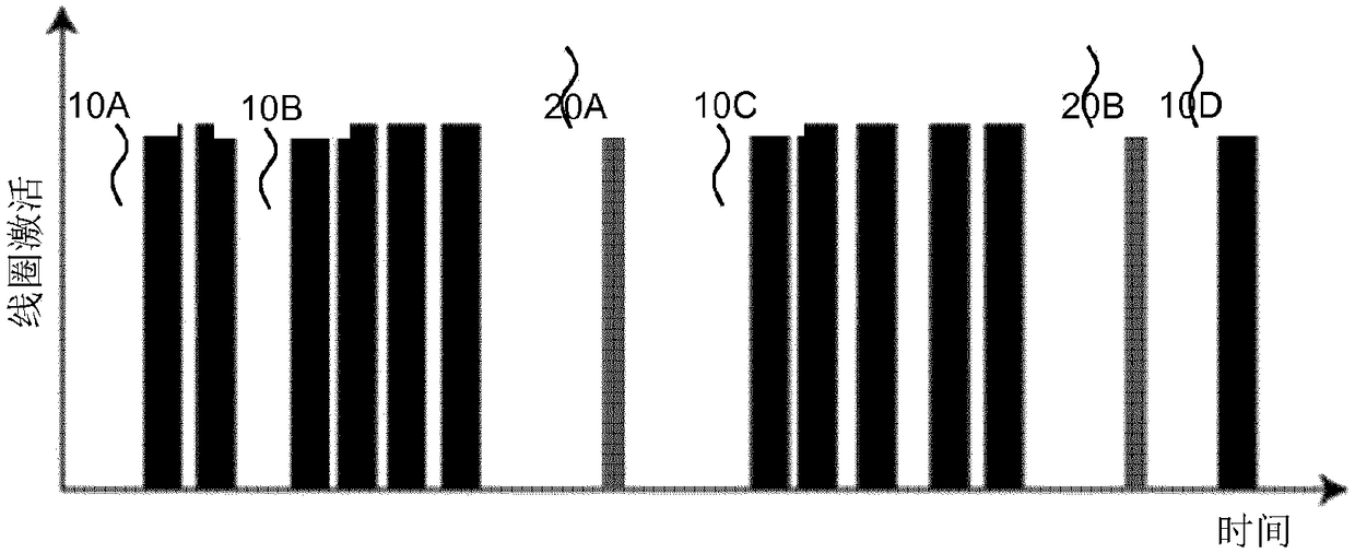
[0064] figure 1 Coil activation over time is shown according to a first embodiment of an aerosol generating system comprising a heating coil and a wick delivering a liquid aerosol-forming substrate from a liquid storage portion to an electric heater. The plots indicate the timing and duration of individual coil activations. The coil may be activated in response to a user generating an aerosol, for example by taking a puff request, or by self-excitation of the electric heater during inactive periods of the electric heater. Coil activation 10A is the first activation of the electric heater caused by the first series of pumps. Coil activation 10B represents the first puff of the second series of puffs occurring after a pause. The pause is short enough that self-excitation of the electric heater cannot occur between the first and second series of puffs initiated by coil activation 10A and 10B. After the second series of puffs, there was a pause long enough for the self-excited ...


PUM


Abstract

The present invention relates to a electrically operated aerosol-generating system for receiving an aerosol-forming substrate, the system comprising a liquid storage portion for storing liquid aerosol-forming substrate, an electric heater comprising at least one heating element for heating the liquid aerosol-forming substrate, and electric circuitry configured to self-activate the electric heaterat a particular time for a self-activation duration in a period of inactivity of the electric heater in order to determine depletion of liquid aerosol-forming substrate based on a relationship betweena power applied to the heating element and a resulting temperature change of the heating element. The present invention further relates to a method of self-activating the electric heater at a particular time for a self-activation duration in a period of inactivity of the electric heater, and determining depletion of liquid aerosol-forming substrate heated by the electric heater based on a relationship between a power applied to the heating element and a resulting temperature change of the heating element. The present invention further relates to an electric circuitry that is arranged to perform the method and a computer readable storage medium.

Description

technical field [0001] The present invention relates to an electrically operated aerosol generating system. In particular, the present invention relates to an electrically operated aerosol generating system wherein the aerosol-forming substrate is a liquid and is contained in a liquid storage portion. Background technique [0002] WO 2012 / 085203 A1 discloses an electrically heated smoking system with a liquid storage portion. The liquid storage portion contains a liquid aerosol-forming substrate and is connected to a vaporizer comprising an electric heater powered by battery power. In use, the electric heater is activated by a user's suction on the mouthpiece to switch on battery power. The heated aerosol-forming substrate contained in the vaporizer will be vaporized. The user's suction on the mouthpiece causes air to be drawn along or through the vaporizer, thus generating an aerosol. The generated aerosol is drawn into the mouthpiece and then into the user's mouth. De...

Claims


Application Information

Patent Timeline
Patent Type & Authority Applications(China)
IPC IPC(8): A24F47/00A24F40/10A24F40/46A24F40/53
CPCA24F40/10A24F40/50A24F40/46A24F40/53A24F40/40A24F40/57A24F40/51A24B15/167A61M15/06
Inventor T·李维尔
Owner PHILIP MORRIS PROD SA
Why Eureka
Try Eureka