
Merging unit based integral error verification system

An overall error and error technology, applied in the field of digital energy meter measurement and inspection, can solve the problems of digital energy meter loss of signal, lack of inspection procedures, measurement loss, etc., to achieve improved sampling rate, high measurement accuracy, and high bandwidth Effect

Inactive Publication Date: 2018-06-08
STATE GRID CHONGQING ELECTRIC POWER CO ELECTRIC POWER RES INST +1
View PDF5 Cites 4 Cited by
  • Summary
  • Abstract
  • Description
  • Claims
  • Application Information

AI Technical Summary

Problems solved by technology

[0004] At present, the relevant verification regulations for digital electric energy meters have not yet been issued. Therefore, in general, in specific engineering applications, the verification of digital electric energy meters refers to electronic multifunctional electric energy meters specified in JJG596 "Verification Regulations for Electronic Multifunctional Electric Energy Meters". Detect load point for accuracy verification
[0005] Existing verification methods have relatively large disadvantages. During verification, the voltage and current signals need to be separately drawn from the merging unit to the reserved verification interface, and then connected to a small switch, and the signals that enter the energy meter from the merging unit are pulled out and connected to the optical fiber. converter, but the digital watt-hour meter will lose signal during the working of the converter, stop measuring, and cause measurement loss
[0006] At the same time, there is currently no statutory inspection procedure and a unified system for comprehensive error inspection of digital electric energy metering devices.

Method used


Image

  • Merging unit based integral error verification system
  • Merging unit based integral error verification system
  • Merging unit based integral error verification system

Examples


Embodiment

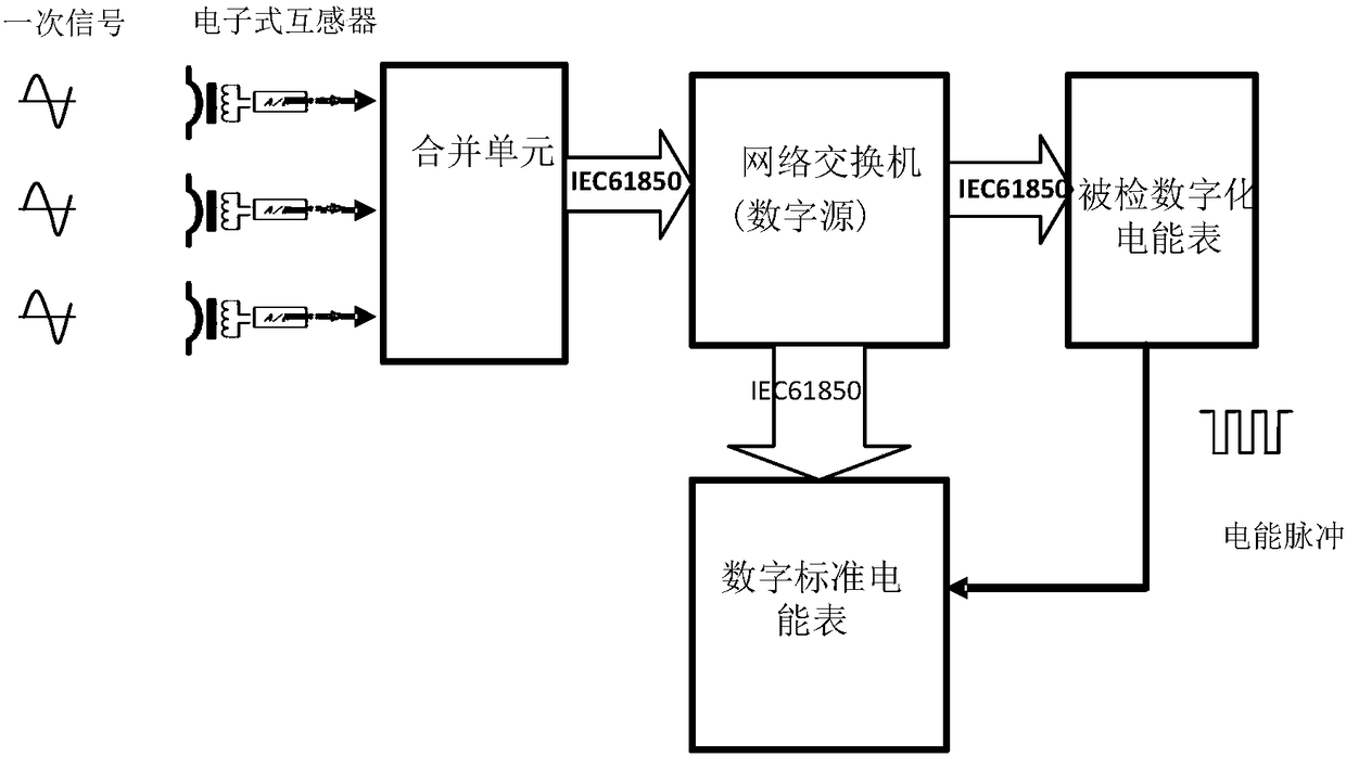
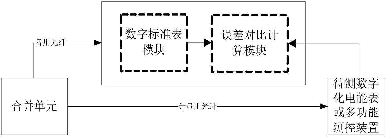
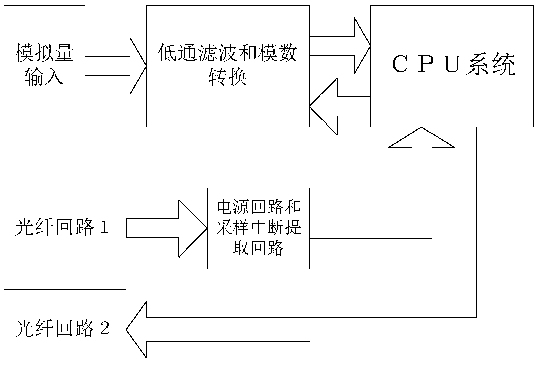
[0047] Example: such as Figure 1 to Figure 8 Shown; a kind of overall error calibration system based on the merging unit, it includes: electronic transformer, merging unit, digital electric energy meter and multifunctional measurement and control device;

[0048] The electronic transformer is connected to the merging unit, and the primary signal detected by the electronic transformer is transmitted to the merging unit;

[0049] The merging unit is connected to the digital electric energy meter to be inspected, and the digital electric energy meter to be inspected is inspected;

[0050] The merging unit is connected to the error comparison calculation module in the standard digital watt-hour meter, and the merging unit checks the digital watt-hour meter to be checked through the error comparison calculation module;

[0051] The merging unit is also connected with the multi-function measurement and control device.

[0052] The electronic transformer includes an electronic cur...


PUM


Abstract

The invention discloses a merging unit based integral error verification system which comprises an electronic mutual inductor, a merging unit, a digital electric energy meter and a multifunctional measurement and control device. The electronic mutual inductor is connected with the merging unit to transmit a primary signal detected by the electronic mutual inductor to the merging unit; the mergingunit is connected with the digital electric energy meter to be detected to detect the digital electric energy meter; the merging unit is connected with an error comparison and calculation module in astandard digital electric energy meter, and verify the digital electric energy meter to be detected via the error comparison and calculation module; and the merging unit is also connected with the multifunctional measurement and control device. The system has the advantages that electric energy is accumulated on the basis of an FT3 message of high sampling rate of the electronic mutual inductor, the sampling value speed of the digital standard meter is improved substantially, electric energy of secondary and harmonic waves is metered, and a test result approaches a real electric energy value more; and a non-pulse verification method is used to improve the operational reliability and stability of metering equipment.

Description

technical field [0001] The invention relates to the technical field of measurement calibration of digital electric energy meters, in particular to an overall error calibration system based on a merging unit. Background technique [0002] At present, the investment scale of the country in the construction of digital substations is increasing, and the demand for electric energy meters in digital substations is also increasing. The digital energy meter with digital input has become an important equipment for electric energy measurement in digital substations. Although some domestic research institutions have developed corresponding calibration equipment, the calibration methods and calibration devices are varied and not uniform enough, and their technical indicators are not yet clear. [0003] In a traditional substation, the electromagnetic transformer outputs an analog voltage and current signal, and the electric energy meter converts the analog quantity into a digital quant...

Claims


Application Information

Patent Timeline
IPC IPC(8): G01R35/04
Inventor 杜杰程瑛颖肖冀侯兴哲宫林冯凌张家铭周峰胡建明
Owner STATE GRID CHONGQING ELECTRIC POWER CO ELECTRIC POWER RES INST
Learn More