
A cam mechanism type ship sloshing simulation device

A technology of cam mechanism and simulation device, which is applied in the direction of measuring device, machine/structural component test, instrument, etc., can solve the problems of complex structure, high cost, and complicated implementation steps, and achieve the goal of less structure and long service life Effect

Active Publication Date: 2019-07-23
ZHEJIANG OCEAN UNIV
View PDF6 Cites 0 Cited by
  • Summary
  • Abstract
  • Description
  • Claims
  • Application Information

AI Technical Summary

Problems solved by technology

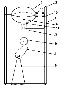
[0005] The present invention designs a simple ship sloshing simulation device using a cam mechanism in view of the complex structure, high cost and complicated implementation steps of the existing ship sloshing simulation device.

Method used

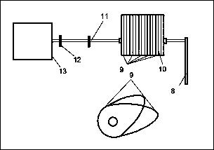

Image

  • A cam mechanism type ship sloshing simulation device
  • A cam mechanism type ship sloshing simulation device
  • A cam mechanism type ship sloshing simulation device

Examples


Embodiment 1

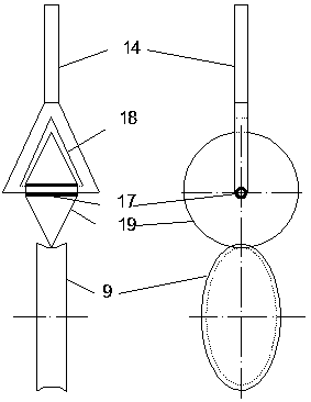
[0024] Such as figure 1 , figure 2 and image 3 As shown, the described a kind of cam 9 mechanism type ship sloshing simulation device includes: a frame 3, a control terminal, a ship model with a magnet, and a sealed hollow ellipsoid experimental cabin 1 that can be made according to the scale ratio. Ship model, the bottom of the ship model is provided with a magnet, and the interior of the ship model is provided with a detection black box; the openable sealed hollow ellipsoid experiment cabin 1 is filled with a simulated environment liquid and a ship model with a magnet is placed inside, and the push rod 14 is installed on the The spherical pair 4 on the side of the experimental cabin 1 is connected to the side shaft 2 through the side bearing 15 arranged on the other side of the experimental cabin; the driven wheel 6 is slidably connected to the power cam group 7 and hinged to the bottom end of the push rod 14; Rod 14, the top is connected with the side of the openable se...

Embodiment 2

[0033] Such as figure 1 , figure 2 , Figure 4 and Figure 5 As shown, embodiment 2 is basically the same as embodiment 1, the difference is that the driven wheel 6 includes: an H-shaped round bracket 20, which is symmetrically installed by two rotating pieces 21 and connected to each other through a connecting rod 22 in the middle, and is arranged in the power The cam group is just above the cam group, it works with the power cam group, and is slidingly connected with the ejector rod bearing 23; 14 fixed connections.


PUM


Abstract

A cam mechanism type ship shaking simulator comprises a frame, a control terminal, a ship model, an experimental chamber, a driven wheel, a top rod, a limiting guide rail, a power cam set, at least one frame bearing group, a side-surface rotating shaft, a side-surface bearing and a detection black box; the bottom of the ship model is provided with a magnet, and the detection black box is arrangedin the ship model; a simulated environment liquid and the ship model are filled into the experimental chamber, the experimental chamber is connected with the top rod via a spherical pair mounted in the side surface of the experimental chamber, and the experimental chamber is connected with the side-surface rotating shaft via the side-surface bearing arranged at the other side of the experimental chamber; the top of the top rod is connected to the side surface of the experimental chamber via the spherical pair, and the bottom of the top rod is hinged to the driven wheel; the limiting guide railis fixedly connected with the frame; the power cam set is arranged under the driven wheel, is in sliding connection with the driven wheel, and is fixedly connected with the frame; the frame bearing group is arranged on the frame and connected to the side-surface rotating shaft; the side-surface rotating shaft is connected with the frame bearing; the middle of the side-surface bearing penetrates the side-surface rotating shaft, and is fixedly connected with the experimental chamber. The simulator includes fewer compositions and is long in service life, and the cam structure can be used to switch different simulated ship shaking motions.

Description

technical field [0001] The device relates to a ship model simulation device, in particular to a cam mechanism type ship sloshing simulation device. Background technique [0002] At present, there are many ship sloshing simulation devices, such as ship two-degree-of-freedom motion platform, ship four-degree-of-freedom motion platform, ship six-degree-of-freedom motion platform, etc., which have compact structure, strong bearing capacity, good rigidity, small error, and dynamic Good performance, etc., but there are also deficiencies such as various composition structures, complex operations, and high production costs, and it also needs to combine robotics, machine tool technology, computer numerical control technology, vibration control technology, multi-coordinate numerical control programming and other technologies; There are many aspects such as position positive solution, flexibility, work space, stiffness and accuracy, dynamic modeling and optimization, control algorithm,...

Claims


Application Information

Patent Timeline
Patent Type & Authority Patents(China)
IPC IPC(8): G01M10/00
CPCG01M10/00
Inventor 朱发新卢金树李玉乐吴文锋郑海林张建伟秦北辰李源
Owner ZHEJIANG OCEAN UNIV
Learn More