
Environment monitoring device

An environmental monitoring and environmental technology, which is applied in the direction of the locking device when the movable parts of the measuring device are not in use, can solve the problems of safety accidents, cumbersome installation and disassembly, unstable fixing, etc., and achieve accident prevention and convenient and quick disassembly Effect

Inactive Publication Date: 2018-06-08
PUJIANG ZHIYIN TECH CO LTD
View PDF0 Cites 1 Cited by
  • Summary
  • Abstract
  • Description
  • Claims
  • Application Information

AI Technical Summary

Problems solved by technology

[0002] Environmental monitoring is an important basis for environmental protection and management. With the rapid development of the economy, more and more people begin to care about the quality of the environment they live in. Through the construction of online monitoring systems for pollution sources and environmental quality, for The management, decision-making and law enforcement supervision of the environmental protection department have special significance for the early warning and prevention of environmental pollution accidents. The automatic environmental protection monitoring station needs to install atmospheric detectors, water quality monitors, UPS and other equipment. The traditional installation method uses bolts, etc. Fasteners are fixed, installation and disassembly are very cumbersome, and the fixation is unstable, prone to fall, causing safety accidents

Method used


Image

  • Environment monitoring device
  • Environment monitoring device
  • Environment monitoring device

Examples


Embodiment Construction

[0016] The preferred embodiments of the present invention will be described in detail below in conjunction with the accompanying drawings, so that the advantages and features of the present invention can be more easily understood by those skilled in the art, so as to define the protection scope of the present invention more clearly.

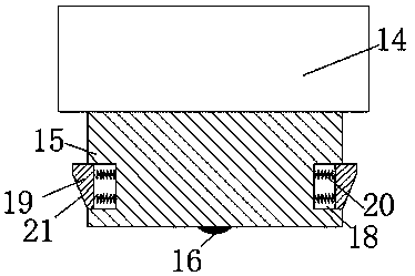
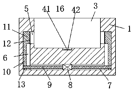
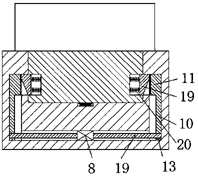
[0017] refer to Figure 1-3 As shown, an environmental monitoring device of the present invention includes a mating cavity 3 arranged in the mounting bracket 1 and a mating column 15 mated with the mating cavity 3, and the top of the mating column 15 is fixedly connected with Environmental monitor 14, the inner bottom wall of the mating chamber 3 is provided with a power connection groove 41, and the electric contact 42 is fixedly arranged in the power connection groove 41, and the left and right side walls of the mating chamber 3 Locking grooves 5 are provided through respectively, and the outer end of the locking grooves 5 is penetrated with a ...


PUM


Abstract

The invention discloses an environment monitoring device which comprises an insertion fit cavity arranged in a mounting bracket and an insertion fit column connected with the insertion fit cavity in amatching manner. The top of the insertion fit column is fixedly connected with an environment monitor. An electricity connecting groove is arranged in the inner bottom wall of the insertion fit cavity. An electrical contact is fixedly arranged in the electricity connecting groove. Locking slots are respectively arranged in the left and right side walls of the insertion fit cavity in a penetratingmanner. A downward extending push-slide slot penetrates the outer end of each locking slot. A transverse slot is arranged in a penetrating manner between the bottoms of the two push-slide slots. A push-slide plate capable of moving transversely is arranged in each push-slide slot. A push-slide block in sliding connection fit with the corresponding locking slot is fixedly arranged on the inner side of the top of each push-slide plate. A wear-resistant pad is fixedly arranged on the inner end face of each push-slide block. A small motor is fixedly arranged in the middle of the transverse slot.The environment monitoring device is simple in structure and convenient to use. The environment monitor can be well fixed, and thus can be prevented from falling off under the action of external forcesuch as high wind to cause accidents and loss.

Description

technical field [0001] The invention relates to the technical field of environment monitoring, in particular to an environment monitoring device. Background technique [0002] Environmental monitoring is an important basis for environmental protection and management. With the rapid development of the economy, more and more people begin to care about the quality of the environment they live in. Through the construction of online monitoring systems for pollution sources and environmental quality, for The management, decision-making and law enforcement supervision of the environmental protection department have special significance for the early warning and prevention of environmental pollution accidents. The automatic environmental protection monitoring station needs to install atmospheric detectors, water quality monitors, UPS and other equipment. The traditional installation method uses bolts, etc. Fasteners are fixed, installation and disassembly are very cumbersome, and th...

Claims


Application Information

Patent Timeline
Patent Type & Authority Applications(China)
IPC IPC(8): G01D11/22
CPCG01D11/22
Inventor 朱华
Owner PUJIANG ZHIYIN TECH CO LTD
Learn More