
Shoe supporting, airing and placing device for balcony

A balcony and strip board technology, which is applied to household cleaning devices, applications, household appliances, etc., can solve the problems of insufficient sunlight exposure time, insufficient sunlight exposure, and poor drying effect.

Inactive Publication Date: 2018-06-08
ZHENGZHOU YOUAI NETWORK TECH CO LTD
View PDF7 Cites 2 Cited by
  • Summary
  • Abstract
  • Description
  • Claims
  • Application Information

AI Technical Summary

Problems solved by technology

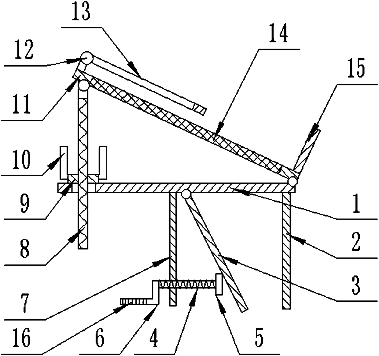
[0002] Nowadays, people live in high-rise commercial buildings, and they set up some drying racks on the balcony to dry clothes, but the effect of drying clothes on the inside of the general balcony is not good, because it is half-open, and the time for sunlight to shine is limited, so it is often necessary to build Some devices for drying clothes are generally fixed horizontally on the railings of the balcony or placed on the ground of the balcony. Since the angle of the sun is changing relative to the balcony within a day, sometimes It is also necessary to place the shoes leaning against the corner of the balcony, in order to be able to expose them to the sun, and the corner is the lower part of the balcony, and the sunlight exposure time is not enough, so it needs to be placed on a high railing, but the railing cannot make the shoes tilt Angled sunlight, so a device that facilitates placing shoes on the rail and also adjusts to an inclined position is needed to solve the problem

Method used


Image

  • Shoe supporting, airing and placing device for balcony
  • Shoe supporting, airing and placing device for balcony
  • Shoe supporting, airing and placing device for balcony

Examples


Embodiment Construction

[0016] The technical solution of this patent will be further described in detail below in conjunction with specific embodiments.

[0017] Embodiments of the present patent are described in detail below, examples of which are shown in the drawings, wherein the same or similar reference numerals designate the same or similar elements or elements having the same or similar functions throughout. The embodiments described below by referring to the figures are exemplary and are only used for explaining the patent, and should not be construed as limiting the patent.

[0018] In the description of this patent, it is to be understood that the terms "center", "upper", "lower", "front", "rear", "left", "right", "vertical", "horizontal", The orientation or positional relationship indicated by "top", "bottom", "inner", "outer", etc. is based on the orientation or positional relationship shown in the drawings, and is only for the convenience of describing this patent and simplifying the des...


PUM


Abstract

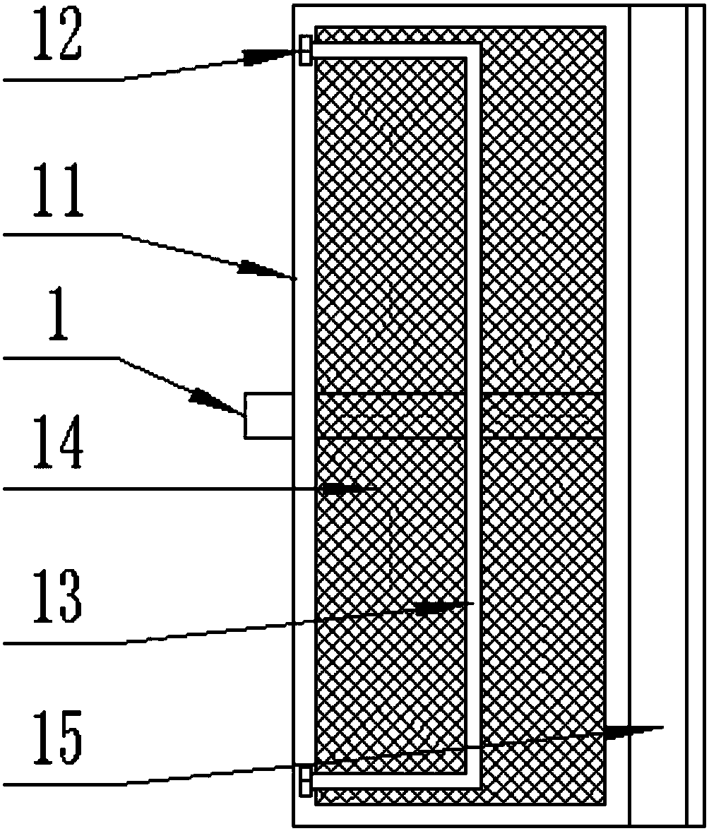
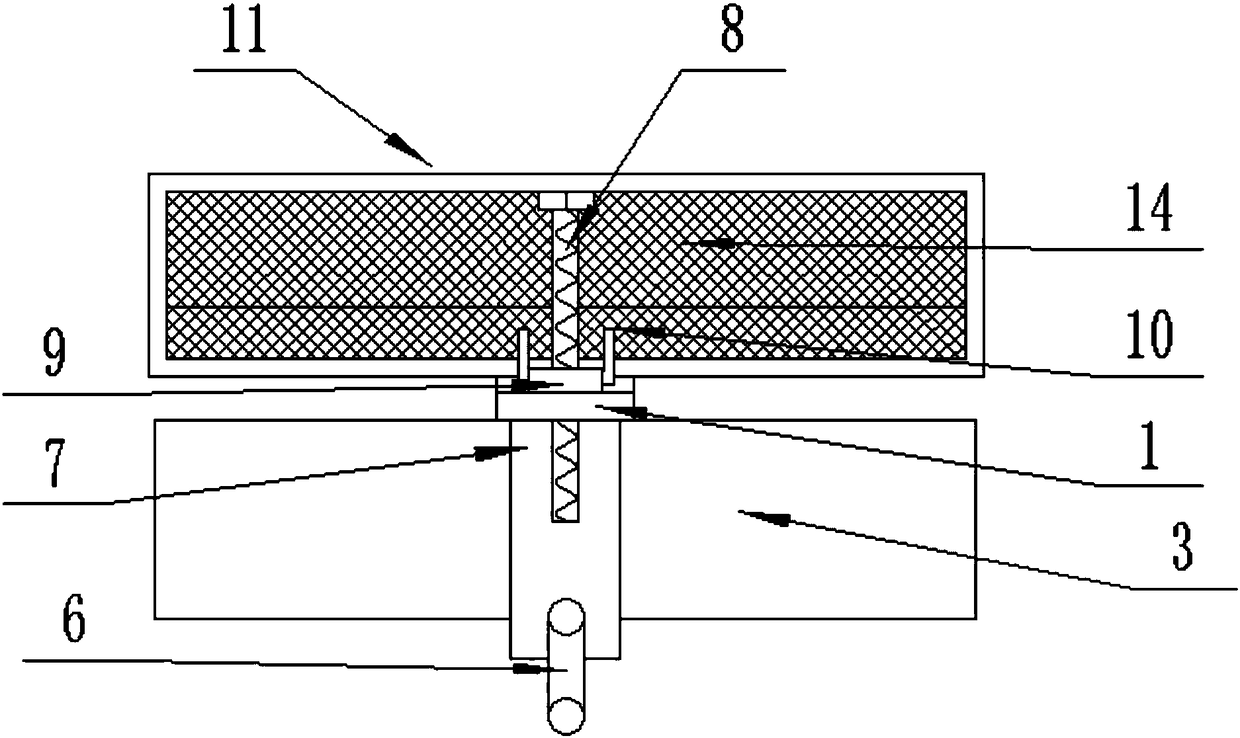
The invention provides a shoe supporting, airing and placing device for balcony, and belongs to the field of home. The shoe supporting, airing and placing device comprises a strip-shaped plate. The strip-shaped plate is located in horizontal positions in the left-right direction, and the right end of the lower end face of the strip-shaped plate is vertically and fixedly connected with a fixed clamping plate. The middle of the lower end face of the strip-shaped plate is vertically and fixedly connected with a connecting plate. A first threaded rod horizontally penetrates through the lower end of the connecting plate in a left-right transverse direction and is fixedly connected with the connecting plate through threads. The left end of the first threaded rod is fixedly connected with a rotating handle. The fixed clamping plate is used for being attached and clamped on the side wall of a guardrail outside the balcony, so the strip-shaped plate is horizontally supported on the guardrail; the antiskid threads are used for increasing the friction force of the side wall of the rotating handle, and the rotating handle is convenient to grab for a user; when the strip-shaped plate is horizontally erected on the balcony guardrail, the first threaded rod is rotated rightward to move so as to rightward eject a movable clamping plate to move, and therefore the movable clamping plate and thefixed clamping plate together clamp a guardrail body of the balcony, and the strip-shaped plate is fixed.

Description

technical field [0001] The invention relates to a household appliance, in particular to a device for drying shoe stretchers for a balcony. Background technique [0002] Nowadays, people live in high-rise commercial buildings, and they set up some drying racks on the balcony to dry clothes, but the effect of drying clothes on the inside of the general balcony is not good, because it is half-open, and the time for sunlight to shine is limited, so it is often necessary to build Some devices for drying clothes are generally fixed horizontally on the railings of the balcony or placed on the ground of the balcony. Since the angle of the sun is changing relative to the balcony within a day, sometimes It is also necessary to place the shoes leaning against the corner of the balcony, in order to be able to expose them to the sun, and the corner is the lower part of the balcony, and the sunlight exposure time is not enough, so it needs to be placed on a high railing, but the railing c...

Claims


Application Information

Patent Timeline
IPC IPC(8): A47L23/20
CPCA47L23/20
Inventor 郜瑶环
Owner ZHENGZHOU YOUAI NETWORK TECH CO LTD
Learn More