Electronic card connector

A connector and electronic card technology, applied in the direction of connection, circuit, contact parts, etc., can solve the problems of insulator damage, affecting product structure stability, weak insulator and other problems

Pending Publication Date: 2018-06-05
SHENZHEN EVERWIN PRECISION TECH
View PDF0 Cites 0 Cited by
  • Summary
  • Abstract
  • Description
  • Claims
  • Application Information

AI Technical Summary

Problems solved by technology

[0003] Since the insulator in the insertion direction of the electronic card is relatively weak, and many electronic cards on the market are obtained by cutting cards, which have many burrs, it is very easy to cause damage to the insulator in the insertion direction during the insertion process of the electronic card, which will affect the overall quality of the product. structural stability

Method used


Image

  • Electronic card connector
  • Electronic card connector
  • Electronic card connector

Examples


Embodiment Construction

[0019] In order to make the purpose, technical solution and advantages of the present application clearer, the technical solution of the present application will be clearly and completely described below in conjunction with specific embodiments of the present application and corresponding drawings. Apparently, the described embodiments are only some of the embodiments of the present application, rather than all the embodiments. Based on the embodiments in this application, all other embodiments obtained by persons of ordinary skill in the art without making creative efforts belong to the scope of protection of this application.

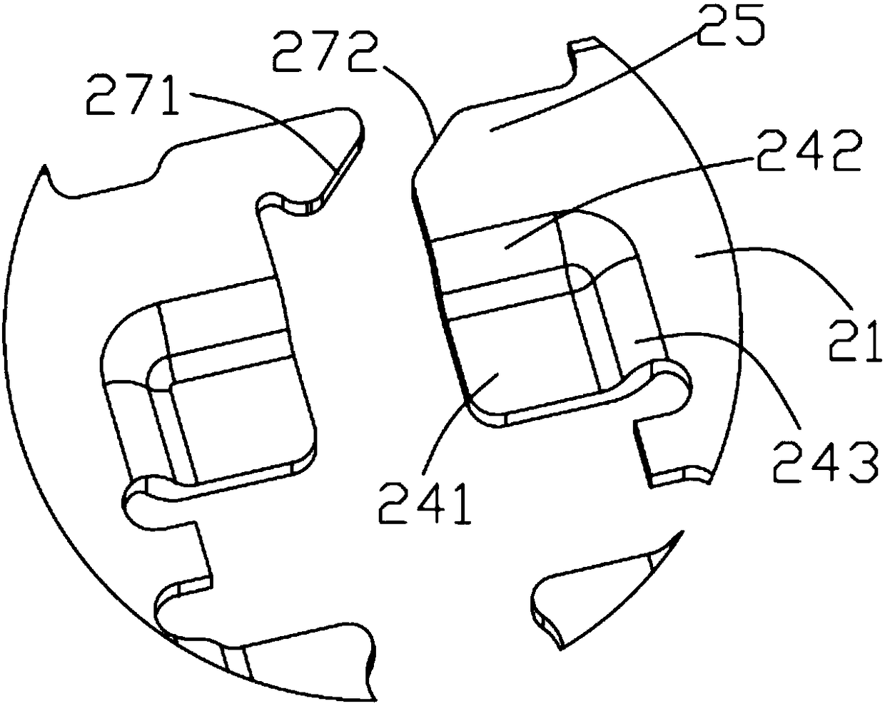
[0020] see Figure 1 to Figure 3 As shown, the electronic card connector of the present application has a plurality of conductive terminals 20 and an insulator 10 in which the plurality of conductive terminals 20 are integrally formed.

[0021] The conductive terminals 20 are arranged in two opposite rows in the longitudinal direction X of the card, ...


PUM


Abstract

An electronic card connector comprises a plurality of conductive terminals and an insulator which integrally forms the plurality of conductive terminals. The conductive terminals are arranged in two opposite rows in the longitudinal direction of card insertion. The insulator comprises a frame body portion and a welding pin accommodating portion formed in the middle of the frame body portion. Eachrow of the conductive terminals comprises two outer side conductive terminals arranged at two ends in the longitudinal direction, and inner conductive terminals arranged between the two outer side conductive terminals. Each conductive terminal comprises a holding portion which is integrally formed in the insulator, two extending arms formed by extending upwardly and obliquely from one lateral sideof the holding portion toward a direction away from the insulator, a contact portion formed by intersecting the two extending arms at a high point, and welding pins extending into the welding pin accommodating portion from the other lateral side of the holding portion. Outer sides of the outer side conductive terminals in the longitudinal direction extend relatively to form reinforcing portions embedded in the insulator. The electronic card connector can effectively strengthen the overall strength and stability of products.

Description

technical field [0001] The present application relates to the field of electrical connectors, in particular to an electronic card connector. Background technique [0002] The Utility Model Patent No. 204088671 of the People's Republic of China discloses a card connector. The card connector includes two rows of oppositely disposed conductive terminals, and an insulator that integrates the two rows of conductive terminals. The conductive terminal includes a holding part formed in the insulator, two extension arms extending from the outside of the holding part, a contact part formed at the intersecting position after the two extension arms extend obliquely upward, and a contact part formed from the holding part. Solder leg formed by inner extension. The middle part of the insulator is formed with a solder fillet receiving portion, and the solder fillet is located in the solder fillet storage portion. [0003] Since the insulator in the insertion direction of the electronic ca...

Claims


Application Information

Patent Timeline
Patent Type & Authority Applications(China)
IPC IPC(8): H01R13/02H01R13/46H01R12/71
CPCH01R13/02H01R12/71H01R13/46
Inventor 樊凌云
Owner SHENZHEN EVERWIN PRECISION TECH
Why Eureka
Try Eureka