Independently dismountable magnetic positioning pendant for decorating curtain wall

A magnetic positioning and pendant technology, which is applied in the direction of walls, building components, coverings/linings, etc., can solve the problems of elastic influence of the spring leaf, T-shaped pendant stuck, difficult to repair, etc., to achieve convenient processing, free positioning, and use The effect of simple method

Pending Publication Date: 2018-06-05
CHONGQING IND POLYTECHNIC COLLEGE
View PDF8 Cites 0 Cited by
  • Summary
  • Abstract
  • Description
  • Claims
  • Application Information

AI Technical Summary

Problems solved by technology

Since the bottom of the stone veneer needs to be supported and stuck by the pre-fixed T-shaped pendant, this method can only be installed one by one from bottom to top. After the installation is completed, if the middle panel is damaged, it is very difficult to repair
Even if the repaired stone veneer is difficult to be stuck by the pre-fixed T-shaped pendant, there is a serious safety hazard
[0003] The patent originally designed by the applicant "A positioning structure for stone decorative panels used with push-in positioning pendants" (Patent No. 2015200227320) fixes the positioning corner blocks on the main body of the pendant and uses spring sheets. If the stone is damaged, The elastic force of the spring sheet may be affected, and when the stone is processed, the added groove must be larger than the thickness of the positioning corner block, and the position of the spring and the positioning nail must be left. If the spring is rusted, it will have a visible hidden safety hazard

Method used


Image

  • Independently dismountable magnetic positioning pendant for decorating curtain wall
  • Independently dismountable magnetic positioning pendant for decorating curtain wall
  • Independently dismountable magnetic positioning pendant for decorating curtain wall

Examples


Embodiment Construction

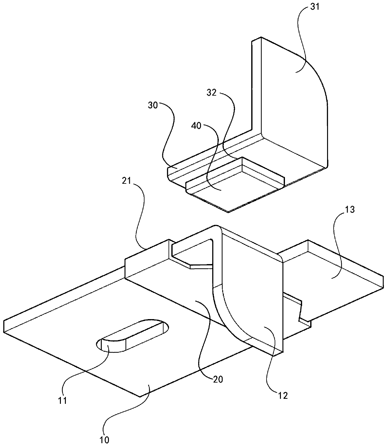
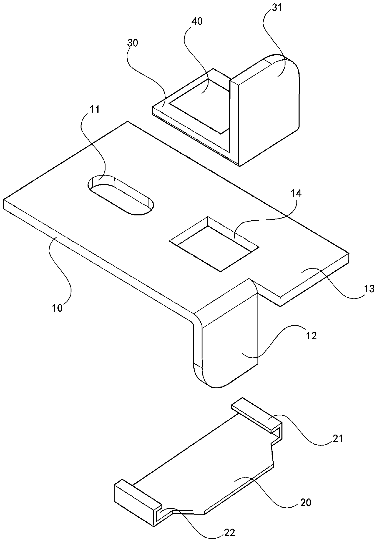
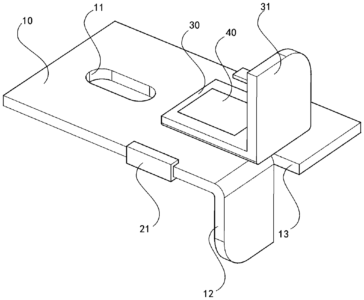
[0013] In the following, the present invention will be further described in conjunction with the drawings and embodiments: Figure 1 to Figure 3 As shown, a separately removable magnetic positioning pendant for decorating curtain walls includes a pendant main body 10, a steel sheet 20, a positioning corner block 30, and a magnet block 40; it is characterized in that the main pendant main body 10 is provided with positioning Adjusting hole 11, downward hook head 12, load-bearing strip 13 and square hole 14 of the pendant body; square hooks 21 are provided on both sides of the steel sheet 20, and the inside of the square hook is in the shape of a square groove 22; the front end of the positioning corner block 30 is provided A positioning corner block square hole 32 is provided in the center of the upward hook head 31; the magnet block 40 is fixed in the positioning corner block square hole 32; the magnet block 40 partially protrudes below the positioning corner block 30; the magne...


PUM


Abstract

The invention discloses an independently dismountable magnetic positioning pendant for decorating a curtain wall. The pendant comprises a pendant main body, a steel sheet, a positioning corner block,and a magnetic block, wherein a positioning regulation hole, a downward hook head, a bearing strip and a pendant main body square hole are arranged on the main pendant main body; square hooks are arranged at two sides of the steel sheet, and the internal of the square hook is a square slot shape; an upward hook head is arranged at the front end of the positioning corner block, and a positioning corner block square hole is arranged in the middle position of the upward hook head; the magnetic block is fixed in the positioning corner block square hole; a part of the magnetic block is protruded atthe lower side of the positioning corner block; the length and width of the part of the magnetic block at the lower side of the positioning corner block are matched with the length and width of the pendant main body square hole; the part of the magnetic block protruded from the positioning corner block can be placed in the pendent main body square hole, and the thickness of the part of the magnetic block protruding to the lower part of the positioning corner lock is consistent with the thickness of the pendant main body. By adopting the positioning pendant disclosed by the invention, the hidden danger that the leaf spring of the former push-in type pendant is rusted and does not work is absent, and the pendant main body can be fixed more stably due to the positioning corner block.

Description

Technical field [0001] The invention relates to a building exterior wall hanger, in particular to a separately detachable magnetic positioning hanger for decorating a curtain wall. Background technique [0002] At present, most of the stone veneer panels are hung on the building by the steel frame dry hanging method. The method is to insert T-shaped pendants into the grooves of the adjacent stone veneers and fill them with adhesive. Since the bottom of the stone veneer needs to be held and stuck by the T-shaped pendant that has been fixed in advance, this method can only be installed one by one from bottom to top. After the installation is completed, if the middle panel is damaged, it is very difficult to repair. Even the repaired stone veneer is difficult to be jammed by the T-shaped pendant fixed in advance, which poses serious safety risks. [0003] The applicant’s original design patent "A stone decorative panel positioning structure for use with push-in positioning pendants" ...

Claims


Application Information

Patent Timeline
Patent Type & Authority Applications(China)
IPC IPC(8): E04B2/88E04F13/14E04F13/30
CPCE04B2/88E04F13/0883E04F13/14
Inventor 欧阳刚苏涛苏姝
Owner CHONGQING IND POLYTECHNIC COLLEGE
Why Eureka
Try Eureka