
Adjusting knob capable of being quickly disengaged and engaged and presser foot height adjustment mechanism

A technology of adjusting the knob and lifting the presser foot, which is applied in the direction of the cloth press mechanism, sewing machine components, textiles and papermaking, etc. It can solve the problems that the height adjustment mechanism of the presser foot cannot be guaranteed to operate reliably, and the reliability of self-locking is poor, so as to achieve reliable self-locking Stable, reliable operation, simple and fast operation

Active Publication Date: 2018-06-05
BULLMER ELECTROMECHANICAL TECH
View PDF6 Cites 2 Cited by
  • Summary
  • Abstract
  • Description
  • Claims
  • Application Information

AI Technical Summary

Problems solved by technology

Generally speaking, the keyhole machine with the height adjustment mechanism of the presser foot will be equipped with an operating part, which can be a knob-adjustable structure, a thread-adjustable structure, a wrench-adjustable structure, etc. However, most of the operating parts Neither of them can achieve fast clutching, so the reliability of self-locking is poor, so that the reliable operation of the presser foot height adjustment mechanism cannot be guaranteed.

Method used


Image

  • Adjusting knob capable of being quickly disengaged and engaged and presser foot height adjustment mechanism
  • Adjusting knob capable of being quickly disengaged and engaged and presser foot height adjustment mechanism
  • Adjusting knob capable of being quickly disengaged and engaged and presser foot height adjustment mechanism

Examples


Embodiment Construction

[0062] The implementation of the present invention will be illustrated by specific specific examples below, and those skilled in the art can easily understand other advantages and effects of the present invention from the contents disclosed in this specification.

[0063] It should be noted that the structures, proportions, sizes, etc. shown in the drawings attached to this specification are only used to match the content disclosed in the specification, for those who are familiar with this technology to understand and read, and are not used to limit the implementation of the present invention. Limiting conditions, so there is no technical substantive meaning, any modification of structure, change of proportional relationship or adjustment of size, without affecting the effect and purpose of the present invention, should still fall within the scope of the present invention. The disclosed technical content must be within the scope covered. At the same time, terms such as "upper"...


PUM


Abstract

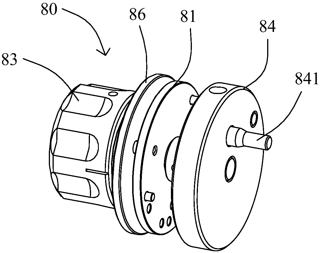
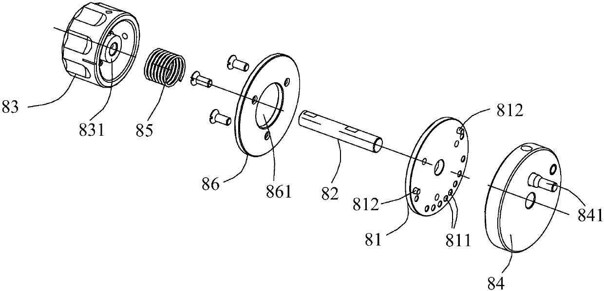
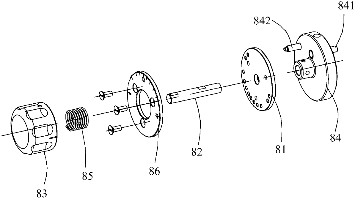
The invention provides an adjusting knob capable of being quickly disengaged and engaged. The adjusting knob comprises an adjusting limiting plate fixed in position, a rotating shaft which rotatably penetrates through the adjusting limiting plate, a knob body fixed at one end of the rotating shaft, an adjusting wheel fixed at the other end of the rotating shaft, and a spring located between the knob body and the adjusting limiting plate; the spring is in a compressed state, and a limiting protruding part is arranged on the end face, facing the adjusting limiting plate, of the adjusting wheel;an eccentric shaft part which is eccentrically arranged with the rotating shaft is arranged on the other end face, back to the adjusting limiting plate, of the adjusting wheel; a limiting concave partfacing the adjusting wheel and matched with the limiting protruding part is formed in the adjusting limiting plate. The adjusting knob can achieve disengagement and engagement between the adjusting wheel and the adjusting limiting plate by pressing or loosening the knob body, and then the whole adjusting knob can be in a self-locked state through the cooperation of the limiting protruding part onthe adjusting wheel and the limiting concave part on the adjusting limiting plate when the knob body is loosened, so that self-locking is reliable and stable, and it is ensured that a presser foot height adjusting mechanism can reliably run only after presser foot height adjustment is completed.

Description

technical field [0001] The present invention relates to an adjusting member, in particular to a fast clutch adjusting knob suitable for a presser foot height adjusting mechanism in a keyhole machine, and a presser foot height adjusting mechanism with the fast clutch adjusting knob. Background technique [0002] The buttonhole machine is a type of industrial sewing machine, which belongs to a special machine, and is mainly used to process buttonholes in various clothing. With the continuous development of technology, the keyhole machine is also developing in the direction of semi-automation and full automation, so its functions are becoming more and more perfect. For example, the keyhole machine is equipped with a presser foot height adjustment mechanism for adjusting The stroke of moving or moving down makes the presser foot mechanism in the buttonhole machine suitable for fabrics of different thicknesses, thereby ensuring the normal operation of the buttonhole machine and h...

Claims


Application Information

Patent Timeline
Patent Type & Authority Applications(China)
IPC IPC(8): D05B29/02
CPCD05B29/02
Inventor 严文进谭炜军
Owner BULLMER ELECTROMECHANICAL TECH
Learn More