
Metal marking machine capable of automatically performing positioning and using method thereof

An automatic positioning and marking machine technology, applied in the direction of metal processing equipment, auxiliary devices, laser welding equipment, etc., can solve the problems of affecting efficiency, the marking position is not accurate enough, and the marking machine lacks positioning devices, etc., so that workers can easily, precise position effect

Active Publication Date: 2018-06-05
MINGGUANG SANYOU ELECTRONICS
View PDF6 Cites 3 Cited by
  • Summary
  • Abstract
  • Description
  • Claims
  • Application Information

AI Technical Summary

Problems solved by technology

[0005] Aiming at the deficiencies of the prior art, the present invention provides an automatic positioning metal marking machine and its use method, which solves the problem that the above-mentioned existing marking machine lacks a positioning device and needs to be held by hand during the marking process. Marking on metal workpieces often leads to inaccurate marking positions, and the workers are tired after working for a long time, which affects the efficiency.

Method used


Image

  • Metal marking machine capable of automatically performing positioning and using method thereof
  • Metal marking machine capable of automatically performing positioning and using method thereof
  • Metal marking machine capable of automatically performing positioning and using method thereof

Examples


Embodiment Construction

[0025] The following will clearly and completely describe the technical solutions in the embodiments of the present invention with reference to the accompanying drawings in the embodiments of the present invention. Obviously, the described embodiments are only some, not all, embodiments of the present invention. Based on the embodiments of the present invention, all other embodiments obtained by persons of ordinary skill in the art without making creative efforts belong to the protection scope of the present invention.

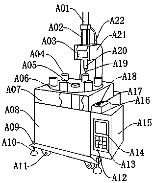
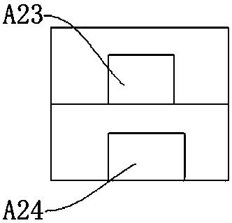
[0026] Such as Figure 1-Figure 3 As shown, a metal marking machine that can be automatically positioned includes a base A09, a chassis A08, a control cabinet A15, and a scanner A21. Wheels A11 are arranged at the four corners of the lower end of the base A09. The base A09 can be moved through the wheels A09, and the base A09 The lower end near the wheel A11 is provided with a support pad A10, and the support pad A10 plays a supporting role. The upper middle p...


PUM


Abstract

The invention provides a metal marking machine capable of automatically performing positioning and a using method thereof. The metal marking machine comprises a base, a machine box, a control cabinetand a scanner, wherein wheels are disposed at four corners of the lower end of the base, and supporting pads are disposed at the positions of the lower end of the base close to the wheels, the middleportion of the upper end of the base is provided with the machine box, and a first motor, a transmission, a second motor, an oil pump and an oil tank are disposed in the machine box. An operating table is disposed at the middle of the upper end of the machine box, a turntable is disposed at the inner middle of the operating table, and a rotating shaft is disposed at the inner middle of the turntable. In the marking machine, the design of the rotating shaft and a positioning block is adopted; and through the setting, the rotating shaft and the positioning block move relative to each other. Evenif a metal workpiece is not square, the metal workpiece can also be driven to move according to a set route, marking work is completed with no position adjustment, mechanized operation is performed in the whole process, the position is more precise, and workers are also more relaxed.

Description

technical field [0001] The invention relates to the field of metal marking machines, in particular to an automatic positioning metal marking machine and a use method thereof. Background technique [0002] Laser marking machine is to use laser beam to make permanent marks on the surface of various materials. The effect of marking is to expose the deep material through the evaporation of the surface material, so as to carve exquisite patterns, trademarks and characters. Laser marking machines are mainly divided into CO2 laser marking machines, semiconductor laser marking machines, and fiber laser marking machines. And YAG laser marking machine, the current laser marking machine is mainly used in some occasions that require finer and higher precision. Used in electronic components, integrated circuits (IC), electrical appliances, mobile communications, hardware products, tool accessories, precision instruments, glasses clocks, jewelry, auto parts, plastic buttons, building mat...

Claims


Application Information

Patent Timeline
IPC IPC(8): B23K26/362B23K26/70B23K37/04
CPCB23K26/361B23K26/702B23K37/0443
Inventor 宋朝阳李辉王波
Owner MINGGUANG SANYOU ELECTRONICS
Learn More