


Quick Research
Generate reliable direction feasibility study reports for your R&D in just a few steps.

Technical Q&A
Discover and master advanced knowledge NOW. Basics, ideas, possibilities, all at once.

Find Solutions
As an expert in R&D theories, this can generate solutions to your technical problems instantly.

Evaluate Feasibility
Analyze your overall solution with one click, know your potential R&D risks in advance.

Monitor Landscape
Get weekly tech updates, stay abreast of the latest tech innovations and key insights.
A kind of wire bending pliers with convenient adjustment
A wire and bending pliers technology, applied in the field of wire bending pliers, can solve problems such as inconvenient carrying, structural defects, and small application range
- Summary
- Abstract
- Description
- Claims
- Application Information
AI Technical Summary
Problems solved by technology
Method used
Image

Examples
Embodiment 1
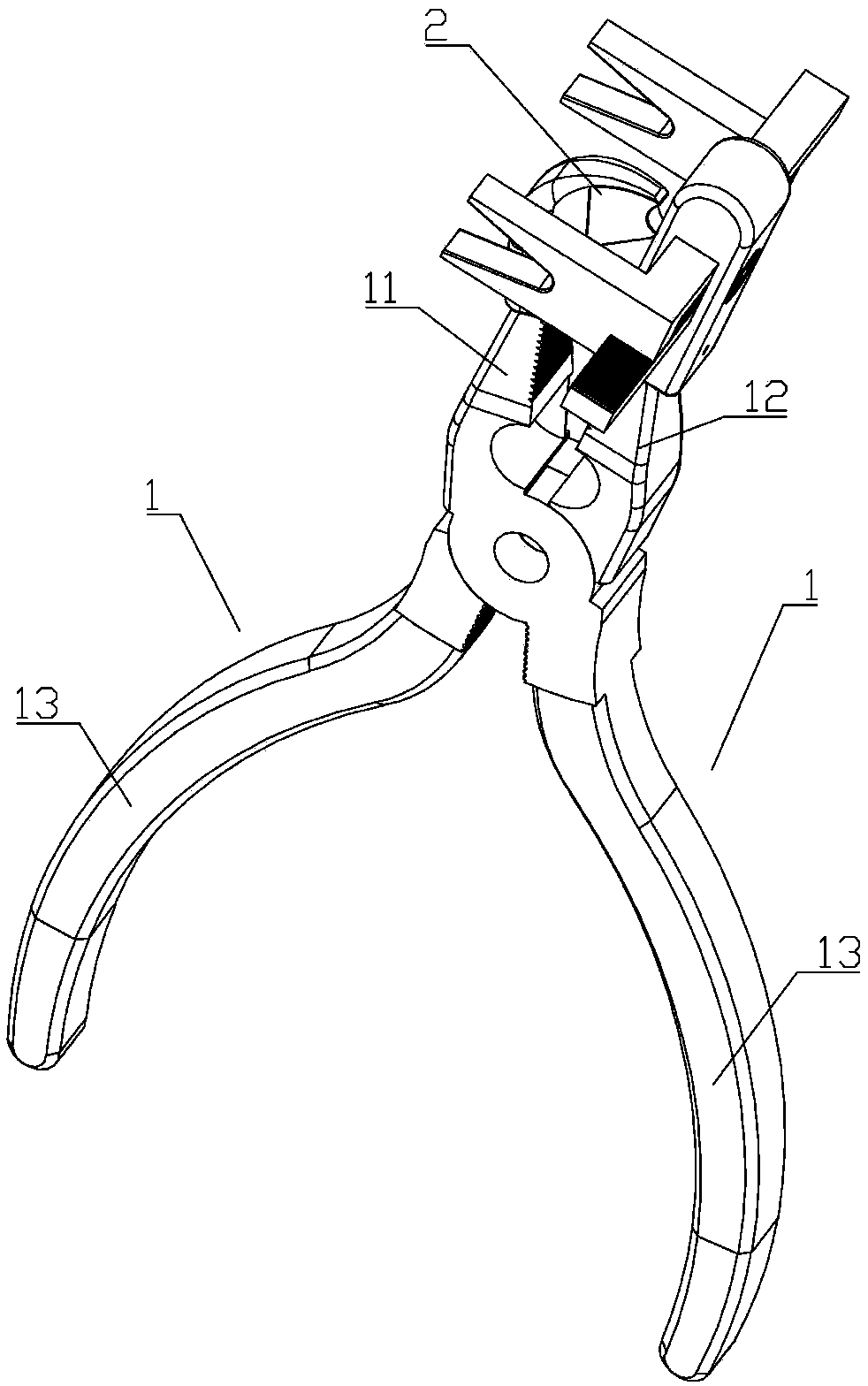
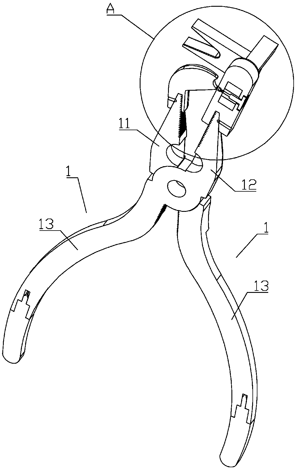
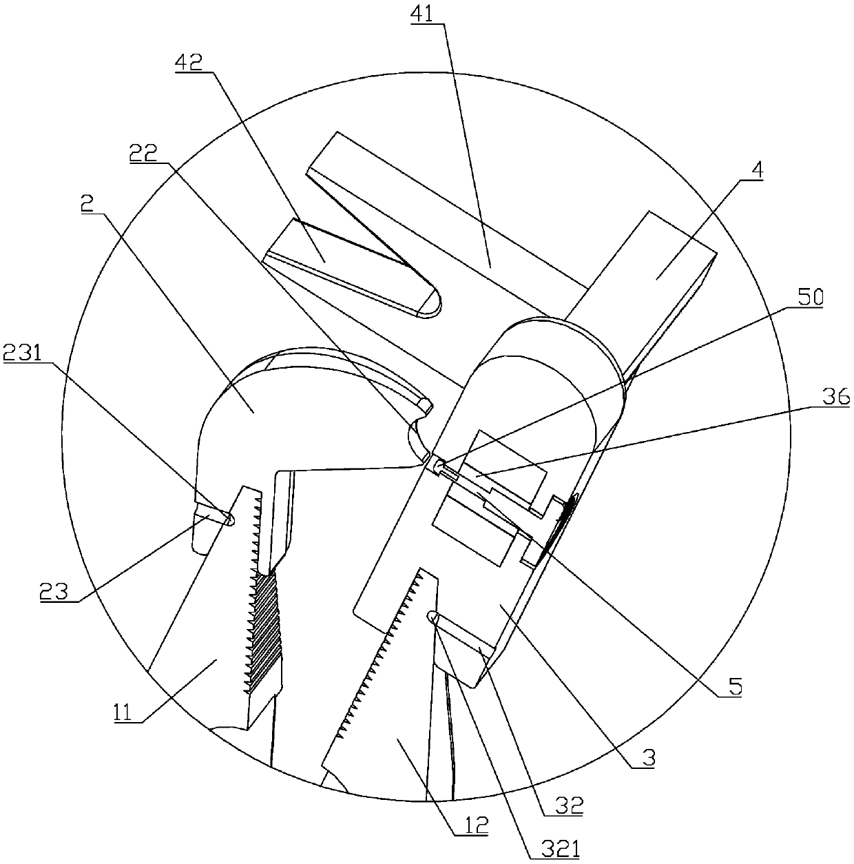
[0038] Such as Figure 1 to Figure 12 As shown, a conveniently adjustable electric wire bending pliers of the present invention includes needle-nose pliers, and the needle-nose pliers include two cross-hinged pliers 1, and the upper ends of the pliers 1 are respectively a left pliers head 11 and a right pliers head 12. The upper ends of the left pliers head 11 and the right pliers head 12 are in the shape of a truncated cone with a small upper part and a larger lower part. The lower end surface of the head 2 is provided with a first conical blind hole 21 matching the upper end of the left pliers head 11, the right end surface of the inverted L-shaped indenter 2 is provided with an arc-shaped gap 22, and the right pliers head 12 is provided with a rectangular block 3, The lower end surface of the rectangular block 3 is provided with a second frustum blind hole 31 matched with the upper end of the right pliers head 12, the upper part of the front end surface of the rectangular b...
Embodiment 2
[0048] Such as Figure 13 As shown, the only difference between this embodiment and the first embodiment is that the inner surface of the clamping block 41 is provided with an opening 43 matching the rectangular block 3 on the side close to the rack 4, and other structures are the same Same as Embodiment 1.
[0049] Such a structural design, when rotating the turntable 52 to drive the two clamping blocks 41 to move to the center, can make the inner side of the clamping block 41 directly above the rectangular block 3, thereby making the distance between the two clamping blocks 41 inner sides It is shorter and can bend wires with smaller angles.
Embodiment 3
[0051] Such as Figure 14 As shown, the only difference between the present embodiment and the second embodiment is that the free end of the rack 4 is provided with a stopper 44 near the side of the gear, and the stopper 44 is provided with a third thread near the end surface of the corresponding rack 4. hole, the rack 4 is provided with a third stepped hole 45 at the position corresponding to the third threaded hole, and a connecting bolt is arranged in the third stepped hole 45, except that, the rest of the structure is the same as that of the second embodiment.
PUM
 Abstract
Description
Claims
Application Information
 - R&D Engineer
- R&D Manager
- IP Professional
- Industry Leading Data Capabilities
- Powerful AI technology
- Patent DNA Extraction
Browse by: Latest US Patents, China's latest patents, Technical Efficacy Thesaurus, Application Domain, Technology Topic, Popular Technical Reports.
© 2024 PatSnap. All rights reserved.Legal|Privacy policy|Modern Slavery Act Transparency Statement|Sitemap|About US| Contact US: help@patsnap.com