
A Design Method for Complex Shell Based on 3D Printing

A technology of three-dimensional printing and design method, which is applied in the field of hydraulic machinery, can solve problems such as time-consuming and affecting the progress of model development, and achieve the effect of oil circuit optimization

Active Publication Date: 2021-02-09
中国航发控制系统研究所
View PDF7 Cites 0 Cited by
  • Summary
  • Abstract
  • Description
  • Claims
  • Application Information

AI Technical Summary

Problems solved by technology

This process, without the support of the forward design method, can only rely on the designer's own ability. Often when the weight cannot meet the input requirements, it takes a lot of time to design for weight reduction, which affects the progress of model development.

Method used


Image

  • A Design Method for Complex Shell Based on 3D Printing
  • A Design Method for Complex Shell Based on 3D Printing
  • A Design Method for Complex Shell Based on 3D Printing

Examples


Embodiment Construction

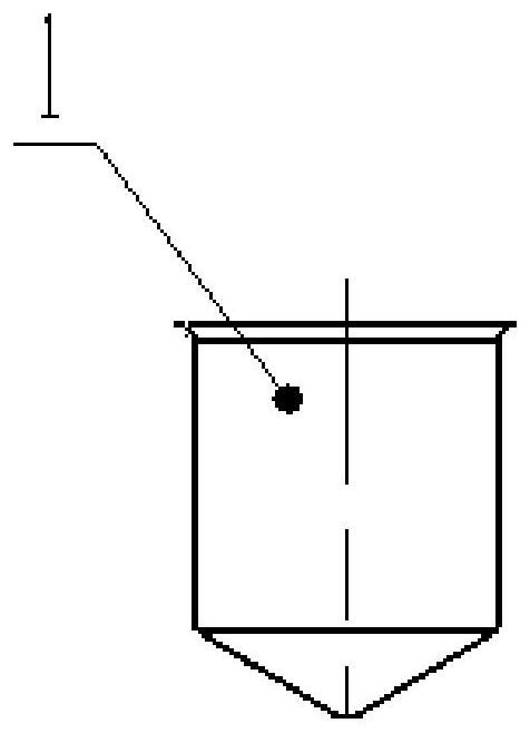
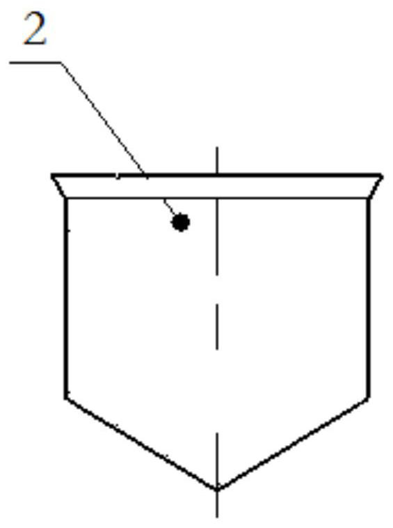
[0040] The present invention will be further described below in conjunction with specific drawings and embodiments. Such as Figure 1-13 as shown,

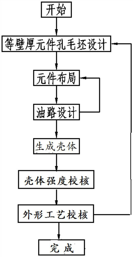
[0041] The present invention provides a complex shell design method based on three-dimensional printing, comprising the following steps:

[0042] 1) Blank design of components with equal wall thickness: According to the selected shell material properties and load conditions, the calculation formula of tensile strength is used to calculate the wall thickness h of the component hole; the three-dimensional structure of the component hole completed by the component designer according to the functional performance requirements of the component Based on the model, in UGS NX software or other 3D structural modeling software, use the related tools of "model enlargement" or "sketch offset curve", and use the calculated wall thickness value h as the enlargement (offset) parameter to complete the component The three-dimensional structural ...


PUM


Abstract

The present invention relates to a complex shell design method based on three-dimensional printing, including the following steps: 1) blank design of components with equal wall thickness; 2) component layout; 3) oil circuit design: according to the oil circuit connection information of the shell schematic diagram, Determine the flow rate required by the oil circuit, and calculate the cross-sectional area required by the oil circuit through the flow formula; 4) generate the shell; 5) check the strength of the shell; 6) check the shape and process. The three-dimensional printing-based three-dimensional design method of the complex casing involved in the present invention can conveniently and quickly realize the volume-weight optimized casing design.

Description

technical field [0001] The invention belongs to the technical field of hydraulic machinery, and relates to a method for designing a complex shell of a hydraulic mechanical device based on three-dimensional printing. Background technique [0002] The hydromechanical device is an important part of the engine control system. Strict requirements such as small size and light weight make the structure of the hydraulic mechanical device extremely complex. Due to the limitation of the installation position and weight of the hydraulic mechanical device, the structure is more compact and the layout is more complicated, which makes the design work more difficult; and in the total weight of the hydraulic mechanical device, the weight of the shell accounts for 50%-60%. [0003] In the past, the three-dimensional design of the shell was generated in the form of material reduction, and the component holes and shapes were removed step by step on a larger blank. The optimization of volume a...

Claims


Application Information

Patent Timeline
Patent Type & Authority Patents(China)
IPC IPC(8): G06F30/20G06F30/17
CPCG06F30/20
Inventor 周毅博陆浩王法全王修专陈静储松林
Owner 中国航发控制系统研究所
Learn More