
An easy-to-operate sandy soil hollow cylinder sample preparation device and sample preparation method

A technology for hollow cylindrical samples and sandy soils, which is applied to sample preparation devices and the field of sample preparation, which can solve the problems of large layer thickness, easy inclination, and obvious differences between layers, etc., to achieve smooth and uniform surface, convenient operation, and simplified sample preparation Process effect

Active Publication Date: 2020-08-11
THE UNIV OF NOTTINGHAM NINGBO CHINA
View PDF11 Cites 0 Cited by
  • Summary
  • Abstract
  • Description
  • Claims
  • Application Information

AI Technical Summary

Problems solved by technology

The disadvantage of vibrating with long plastic rods is that it is difficult to control the thickness of each layer, and the flatness of the layer is difficult to control, etc.; and the disadvantage of the annular indenter compactor is that the latex film on the inner and outer walls is easily damaged by repeated removal of the installation indenter; it is difficult to effectively It is suitable for the case of a large number of layers, so that the thickness of the layer is relatively large and the difference between the layers is more obvious, which affects the uniformity of the sample; and the larger layer thickness is often combined with a heavy hammer with a larger self-weight, which makes the impact force of the hammer larger , it is easy to cause problems such as internal cracks in the sample
In addition, the internal mold provided by the manufacturer is composed of a double-valve internal mold and a pumping plate. The lower end is embedded in a shallow groove, and the upper end is not restrained. It is easy to tilt in the early stage of sample preparation, resulting in inconsistent wall thickness of the sample.

Method used


Image

  • An easy-to-operate sandy soil hollow cylinder sample preparation device and sample preparation method
  • An easy-to-operate sandy soil hollow cylinder sample preparation device and sample preparation method
  • An easy-to-operate sandy soil hollow cylinder sample preparation device and sample preparation method

Examples


Embodiment Construction

[0031] The present invention will be further described in detail below in conjunction with the accompanying drawings and embodiments.

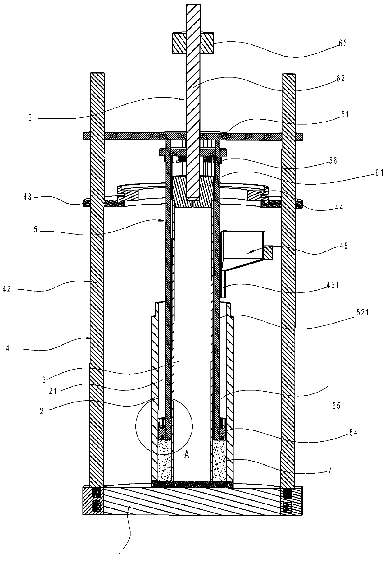
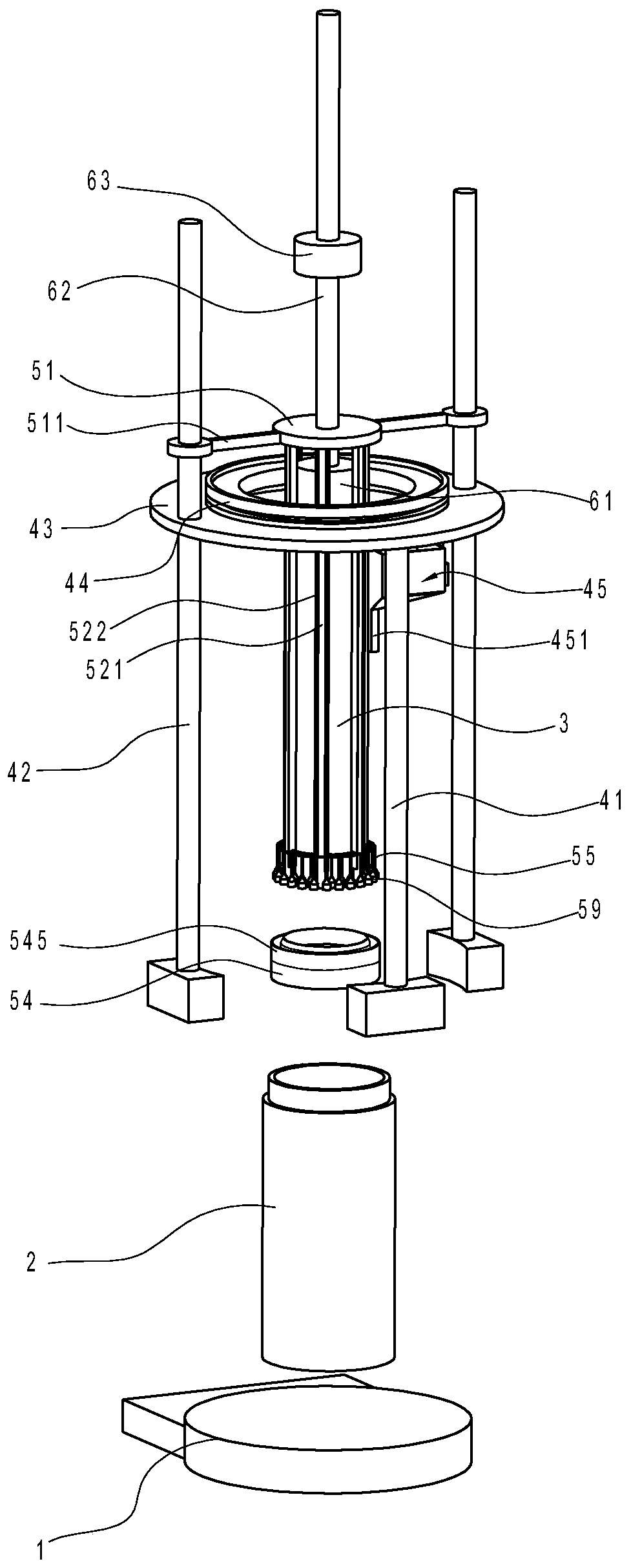
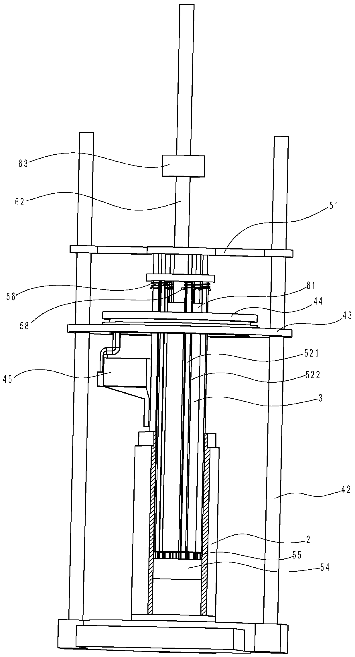
[0032] Such as Figures 1 to 8As shown, the easy-to-operate hollow cylindrical sample preparation device for sand and soil in this implementation includes a base 1 , an outer mold 2 , an inner mold 3 , a blanking assembly 4 , an unloading compaction assembly 5 and a tamping assembly 6 .

[0033] Wherein, the outer mold 2 is composed of three-lobed circular stainless steel metal sheets with a central angle of 120° of a certain thickness, and is fixed by upper and lower clamping rings. The inner mold 3 is composed of two semicircular stainless steel cylinders and a stainless steel pumping plate butt joint. The bottom ends of the outer mold 2 and the inner mold 3 are embedded in the annular shallow groove on the top surface of the base 1 . The inner mold 3 is arranged in the outer mold 2 , and a sample cavity 21 for forming a sample is formed b...


PUM


Abstract

The invention discloses an easy-to-operate hollow sand cylinder sample preparation device and method. The sample preparation device comprises a base, an outer mold, an inner mold, a blanking assembly,a discharge compaction assembly and a tamping assembly, wherein the blanking assembly comprises an annular fixing plate, a rotary table is rotationally arranged in a through hole in the annular fixing plate, and a funnel is arranged below the rotary table; the discharge compaction assembly comprises a bearing plate, an annular pressure head and force transmission rods, a piston is arranged in theannular pressure head, and a sleeve rod is glidingly arranged outside each force transmission rod in a sleeving manner; the tamping assembly comprises a scale rod, and the scale rod is glidingly sleeved with a tamping rod. The sample preparation method comprises the following steps: the discharge compaction assembly is raised to a certain height along guide rods, sand is uniformly sprayed to theupper end face of the annular pressure head, the sand above the annular pressure head falls into the bottom of a sample cavity, the bottom of the annular pressure head is pressed above the sand in thesample cavity, and a rammer is dropped repeatedly.

Description

technical field [0001] The invention relates to a sample preparation device and a sample preparation method thereof, in particular to an easy-to-operate sandy soil hollow cylinder sample preparation device and a sample preparation method thereof. Background technique [0002] In the process of sample preparation for sandy soil hollow cylinder test, the commonly used sample preparation method is the layered compaction method. The compaction tool is generally a long plastic vibrator or a ring-shaped head compactor. The disadvantage of vibrating with long plastic rods is that it is difficult to control the thickness of each layer, and the flatness of the layer is difficult to control, etc.; and the disadvantage of the annular indenter compactor is that the latex film on the inner and outer walls is easily damaged by repeated removal of the installation indenter; it is difficult to effectively It is suitable for the case of a large number of layers, so that the thickness of the...

Claims


Application Information

Patent Timeline
Patent Type & Authority Patents(China)
IPC IPC(8): G01N1/28
CPCG01N1/286
Inventor 王娟刘姝陈旭宏熊衍飞朱伟强
Owner THE UNIV OF NOTTINGHAM NINGBO CHINA
Learn More