
Electronic simulation candle

An electronic simulation and candle technology, which is applied in the field of lighting, can solve the problems of easy falling off of flame pieces, insufficient fragrance, and low production efficiency, and achieve the effects of reducing production costs and defect rates, simple mold structure, and improving production efficiency

Active Publication Date: 2018-06-01
GUANGDONG YAYI SEMICON APPLIED SCI & TECH CO LTD
View PDF6 Cites 8 Cited by
  • Summary
  • Abstract
  • Description
  • Claims
  • Application Information

AI Technical Summary

Problems solved by technology

[0003] Existing electronic simulation candles simulate the flame of traditional candles by irradiating light from LEDs onto the flame sheet. The flame sheet is generally hung on a hook made of metal wire and swings back and forth. This structure is complicated to install and low in production efficiency, resulting in production costs. high
There are also some flame sheets that use hooks. This structure will lead to problems such as complex molds, high defect rates, and easy falling off of flame sheets.
[0004] In addition, some electronic simulation candles also use fans to blow essential oils to fill the room with fragrance, but the range of fragrance is small, and the fragrance is not strong enough.

Method used


Image

  • Electronic simulation candle
  • Electronic simulation candle
  • Electronic simulation candle

Examples


Embodiment Construction

[0024] The following will clearly and completely describe the technical solutions in the embodiments of the present invention with reference to the drawings in the embodiments of the present invention.

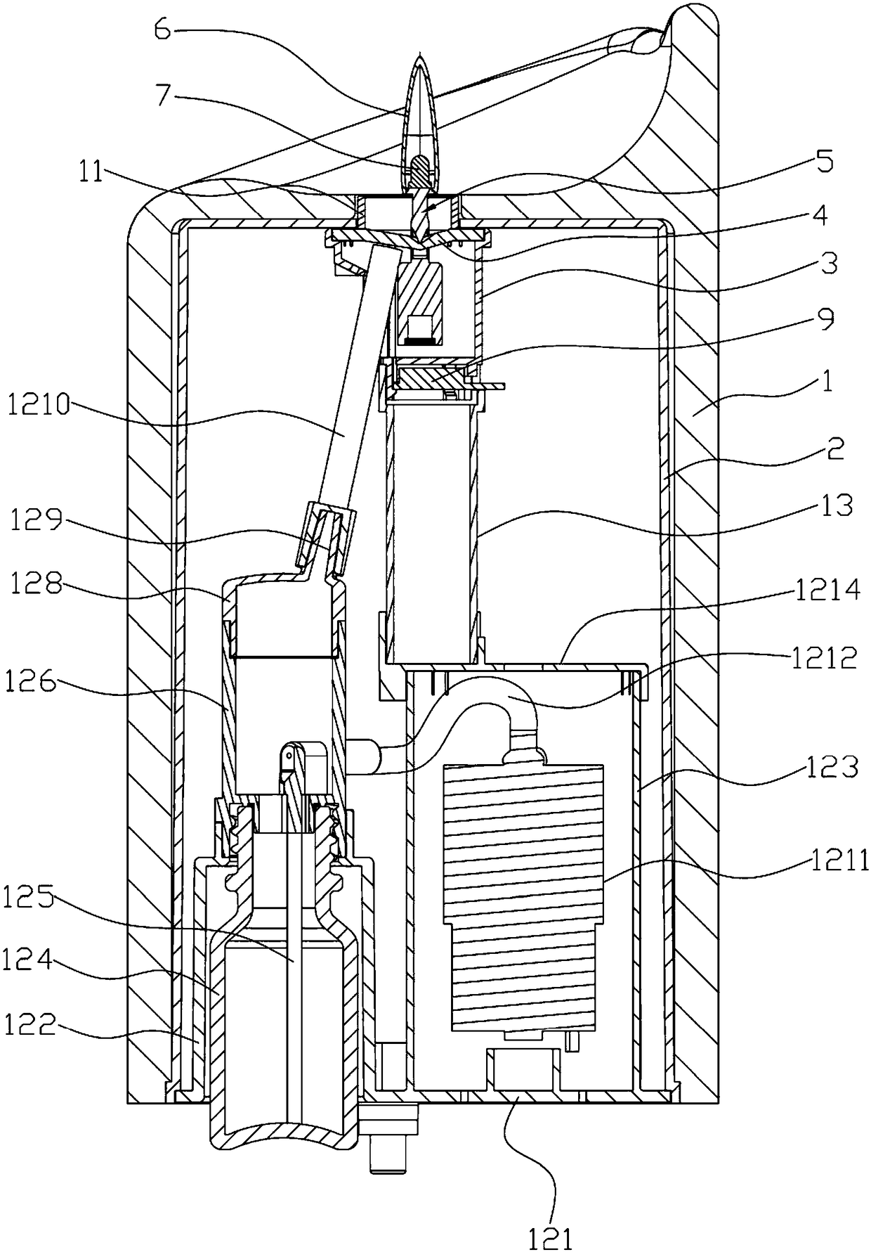
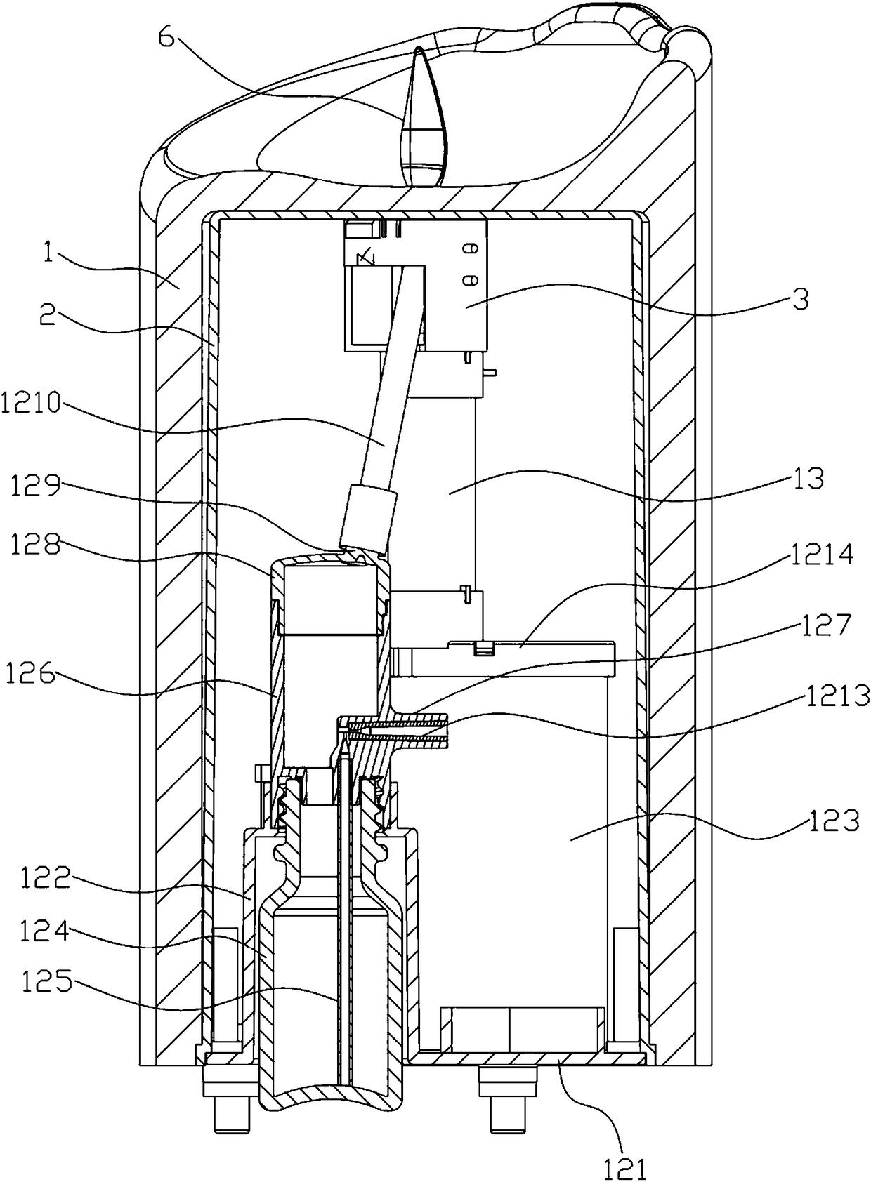
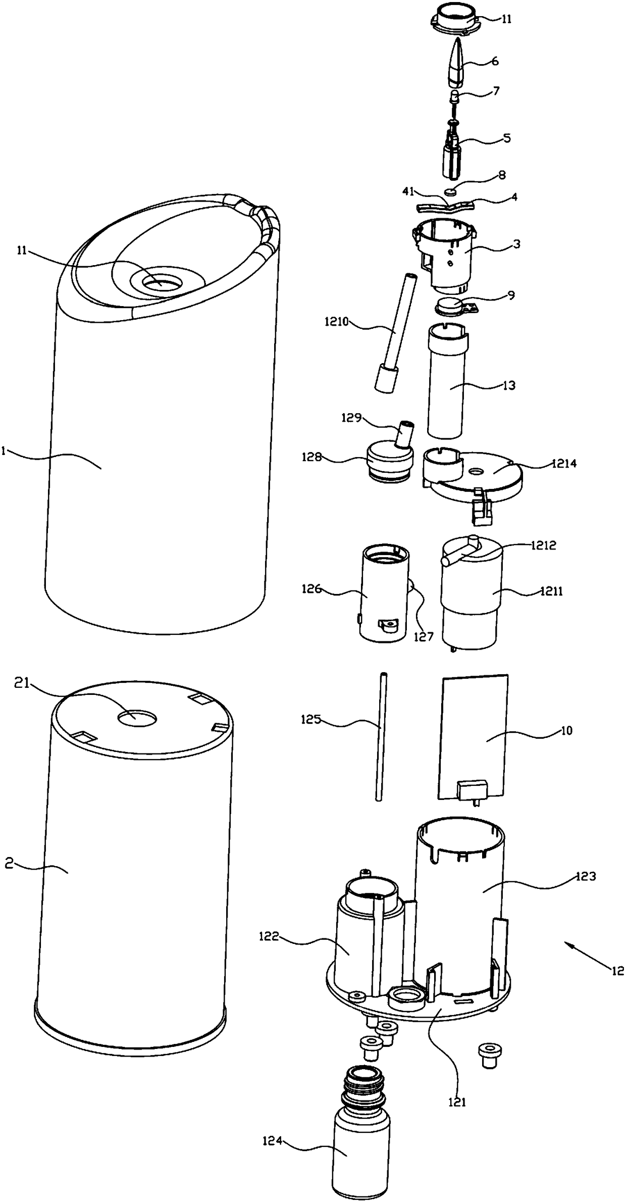
[0025] like Figure 1 ~ Figure 4 As shown, an electronic simulation candle provided by the embodiment of the present invention includes a wax cylinder 1 and a cylinder body 2. Both the wax cylinder 1 and the cylinder body 2 are hollow structures with a closed top and an open bottom, and the wax cylinder 1 is sleeved on the cylinder body. 2. On the outer surface, a first through hole 21 is opened on the top of the cylinder 2, and a second through hole 11 is opened on the top of the wax cylinder 1. The first through hole 21 and the second through hole 11 are arranged opposite to each other and communicate with each other. 2 The inner surface of the top is fixed with an installation cylinder 3 located in the cylinder body 2. The installation cylinder 3 is a hollow structure with ...


PUM


Abstract

The invention discloses an electronic simulation candle which comprises a barrel body; a first through hole is formed in the top of the barrel body; a mounting barrel is fixedly arranged at the innersurface of the top of the barrel body; the top of the mounting barrel is connected with a strip-shaped first bracket in a buckling manner; the first bracket is arranged in the radial direction of themounting barrel; a second bracket capable of swinging freely is hung on the first bracket; the upper part of the second bracket penetrates through a second through hole and the first through hole; thelower part of the second bracket is arranged in the barrel body; a hollow and transparent flame cover is fixedly arranged at the top of the second bracket; at least one LED is fixedly arranged in theflame cover; at least one magnet block is fixedly arranged at the lower end of the second bracket; an electromagnetic coil is fixedly arranged at the bottom of the mounting barrel; and the LED and the electromagnetic coil are electrically connected with a power supply control board separately. The first bracket is connected with the mounting barrel conveniently and stably, so that the situation that the second bracket swings on the first bracket stably in a long term is ensured; and the first bracket and the mounting barrel are subjected to mass production independently, so that the production cost and the reject ratio are lowered and the production efficiency is improved.

Description

technical field [0001] The invention belongs to the technical field of lighting, in particular to an electronic simulation candle. Background technique [0002] In order to pursue a comfortable and elegant living space, people are very particular about the structure of the indoor environment atmosphere, and often use electronic simulation candles to change the indoor environment atmosphere. [0003] Existing electronic simulation candles simulate the flame of traditional candles by irradiating light from LEDs onto the flame sheet. The flame sheet is generally hung on a hook made of metal wire and swings back and forth. This structure is complicated to install and low in production efficiency, resulting in production costs. high. There are also some flame sheets that use hooks. This structure will lead to problems such as complex molds, high defect rates, and easy falling off of the flame sheets. [0004] In addition, some electronic simulation candles also use fans to blow...

Claims


Application Information

Patent Timeline
Patent Type & Authority Applications(China)
IPC IPC(8): F21S10/04F21V14/02F21V19/00A61L9/04A61L9/14F21Y115/10
CPCA61L9/04A61L9/14F21S10/046F21V14/02F21V19/001F21Y2115/10
Inventor 吴文锋蔡海成王伟
Owner GUANGDONG YAYI SEMICON APPLIED SCI & TECH CO LTD
Learn More