Fibre optic fusion splicer

一种光纤熔接机、光纤的技术,应用在光纤熔接领域,能够解决电极棒或V-槽破损等问题,达到消除排列误差的效果

Active Publication Date: 2018-05-29
SOLTECH INFONET
View PDF5 Cites 0 Cited by
  • Summary
  • Abstract
  • Description
  • Claims
  • Application Information

AI Technical Summary

Problems solved by technology

However, according to the Laid-Open Patent Gazette, the electrode rod or the V-groove often becomes the cause of breakage during the process of separating the optical fiber from the fusion splicer after splicing

Method used


Image

  • Fibre optic fusion splicer
  • Fibre optic fusion splicer
  • Fibre optic fusion splicer

Examples


Embodiment Construction

[0033] Other objects, features, and advantages of the present invention will be clarified through the detailed description of the embodiments with reference to the accompanying drawings.

[0034] Below, the structure and function of the embodiments of the present invention will be described with reference to the accompanying drawings. The structure and function of the present invention illustrated and illustrated with the help of figures can be described as at least one embodiment. Its core composition and function are not limited by the above description.

[0035] Hereinafter, preferred embodiments of the optical fiber fusion splicer according to the present invention will be described in detail with reference to the accompanying drawings.

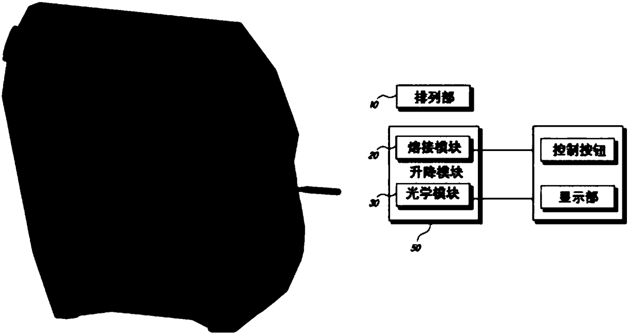
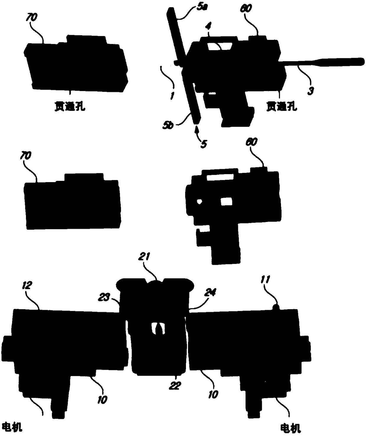
[0036] figure 1 In order to show the perspective view and block diagram of the overall composition of the optical fiber fusion splicer according to the present invention, figure 2 It is a perspective view showing the structure of the ...


PUM


Abstract

The present invention relates to a fiber optic fusion splicing technique, in particular to a fiber optic fusion splicer for reliable and stable fiber optic fusion splicing, that is characterized by comprising: an alignment part for fixing and aligning first and second optical fibers that are to be fusion spliced; a fusion splicing module having an electrode bar for fusion splicing the first and second optical fibers that are fixed to and aligned in the alignment module; an optical module for photographing the aligned state of the first and second optical fibers aligned by the alignment module,and the fusion-spliced state of the first and second optical fibers fusion-spliced by the fusion splicing module; a support part in which the fusion splicing module and the optical module are mounted; and a lift module for moving the support part up and down.

Description

technical field [0001] The invention relates to optical fiber fusion splicing technology, in particular to an optical fiber fusion splicer for realizing reliable and stable optical fiber fusion splicing. Background technique [0002] Typically, optical fibers (or optical cables) are used to transmit optical signals, unlike cables that transmit electrical signals, and can transmit large-capacity information at ultra-high speed without loss. [0003] Because manufacturers cannot manufacture optical cables in an infinitely long manner, they are usually manufactured as 2km-long optical cables and wound on drums. Therefore, in order to install optical cables far away, they need to be connected or branched in the middle. [0004] However, the core of an optical cable is composed of optical fibers with a very small diameter, so it is difficult to connect the optical fibers. [0005] As methods for connecting optical fibers, there are mainly a fusion splicing method using an optica...

Claims


Application Information

Patent Timeline
Patent Type & Authority Applications(China)
IPC IPC(8): G02B6/255
CPCG02B6/2553G02B6/2558G02B6/3833G02B6/3846G02B6/255G02B6/38G02B6/3837G02B6/3838G02B6/3847G02B6/2555G02B6/3616
Inventor 李昌勋尹庚镇宣京浩朴炳哲李彰培李知溒
Owner SOLTECH INFONET
Why Eureka
Try Eureka