A Method for Automatic Correction of Initial Wavelength of Optical Fiber Sensor

A fiber optic sensor and sensor technology, applied in the direction of converting sensor output, using optical devices to transmit sensing components, instruments, etc., can solve problems such as the inability to accurately and effectively capture bridge structural health and safety information, hidden safety hazards, and abnormal monitoring data

Active Publication Date: 2021-01-26
CCCC ROAD & BRIDGE CONSULTANTS
View PDF5 Cites 0 Cited by
  • Summary
  • Abstract
  • Description
  • Claims
  • Application Information

AI Technical Summary

Problems solved by technology

However, due to the fact that the actual initial wavelength of the fiber optic sensor will change during the transportation and installation process, if the initial wavelength provided by the manufacturer is used for calculation at the beginning of data collection and calculation, it will cause a large deviation in the calculation result, making The monitoring data is abnormal, and the problems existing in the bridge structure cannot be found in time, and the accurate data support for the safety evaluation of the bridge cannot be provided.
[0003] At present, the initial wavelength correction methods of fiber optic sensors are all manually calculated and corrected based on the collected data one by one. However, due to the large number of fiber optic sensors routinely used in the monitoring system, each correction will consume a lot of time and effort. In addition, the data collected by the system during this period are all abnormal data, which will lead to the inability to accurately and effectively capture the health and safety information of the bridge structure, resulting in greater safety hazards

Method used


Image

  • A Method for Automatic Correction of Initial Wavelength of Optical Fiber Sensor
  • A Method for Automatic Correction of Initial Wavelength of Optical Fiber Sensor
  • A Method for Automatic Correction of Initial Wavelength of Optical Fiber Sensor

Examples


Embodiment Construction

[0018] The present invention will be further described in detail below in conjunction with the accompanying drawings and specific embodiments.

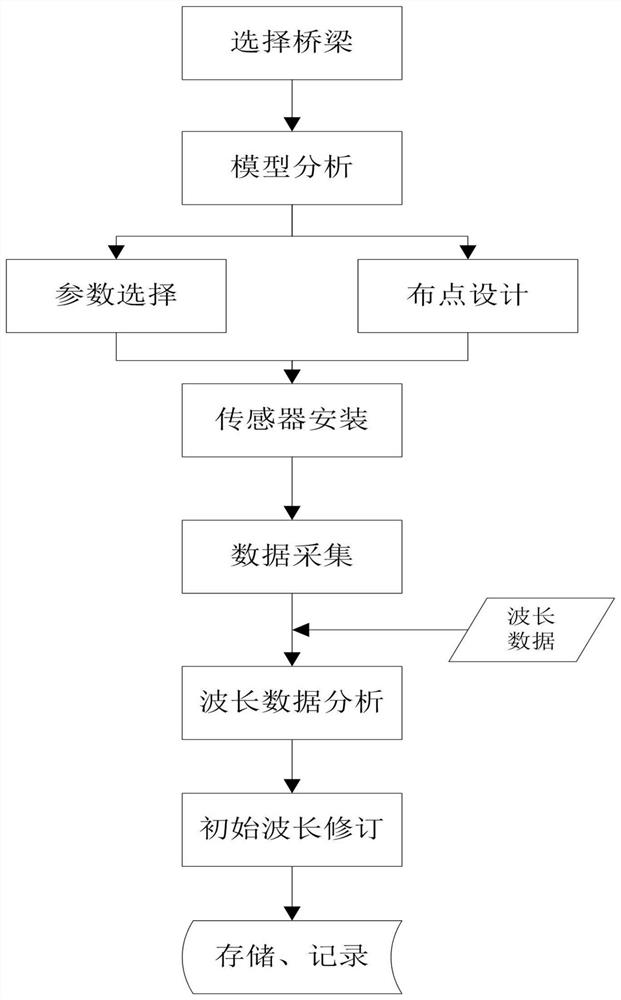
[0019] figure 1 A method for automatically correcting the initial wavelength of an optical fiber sensor is shown, and its specific steps are:

[0020] Step S1, select the bridge to be monitored, analyze its structure, and determine the monitoring items;

[0021] Step S2, select the corresponding optical fiber sensor according to the monitoring item, select the parameters of the optical fiber sensor and design the layout, and install the optical fiber sensor at the corresponding measuring point position;

[0022] Step S3, collect the strain, deformation and displacement signals of the bridge structure through the fiber optic sensor, and then convert the signal collected by the fiber optic sensor into real-time wavelength data through the fiber grating demodulator;

[0023] Step S4. Select the wavelength data from 1:00 to 4:00 in the ...


PUM


Abstract

The invention discloses a method for automatically correcting the initial wavelength of an optical fiber sensor. The overall steps are: select a monitoring bridge; install a corresponding optical fiber sensor; collect bridge structure signals through the optical fiber sensor, and then collect the optical fiber sensor to the Convert the signal into real-time wavelength data; draw the wavelength data curve; divide the period of external vehicle load and no load; select the period of no load within 10 to 30 minutes as the initial wavelength calculation period; select the initial wavelength calculation period The wavelength data of the last 1 to 5 minutes within the last 1 to 5 minutes is averaged, and the averaged value is taken as the new initial wavelength of the sensor. The invention solves the problem that the wavelength of the optical fiber sensor drifts with time, makes the monitoring data of the sensor reflect the bridge structure more realistically, facilitates bridge maintenance and management personnel to more timely and scientifically analyze the problems existing in the structure, and escorts the safe operation of the bridge.

Description

technical field [0001] The invention relates to a correction method, in particular to an automatic correction method of an initial wavelength of an optical fiber sensor, and belongs to the technical field of bridge health monitoring. Background technique [0002] At present, fiber optic sensors are widely used in the field of bridge structural health monitoring. Fiber optic sensors will become the mainstream direction of sensor development in the field of structural health monitoring in the future due to their superior anti-interference performance, high sensitivity, good stability, and long service life. However, due to the fact that the actual initial wavelength of the fiber optic sensor will change during the transportation and installation process, if the initial wavelength provided by the manufacturer is used for calculation at the beginning of data collection and calculation, it will cause a large deviation in the calculation result, making The monitoring data is abnor...

Claims


Application Information

Patent Timeline
Patent Type & Authority Patents(China)
IPC IPC(8): G01D21/02G01D5/353G01D3/036
CPCG01D3/036G01D5/35316G01D21/02
Inventor 杨书仁张娜姚建群杨圣超
Owner CCCC ROAD & BRIDGE CONSULTANTS
Why Eureka
Try Eureka