Novel supporting cushion block for steam generator

A technology for steam generators and supporting pads, which is applied in the field of nuclear power plants, can solve problems affecting the correctness of clearance adjustment, excessive thermal stress of units, and inconsistency between stress state and design, so as to improve measurement accuracy, improve reliability, reduce The effect of uncertainty

Pending Publication Date: 2018-05-29
CHINA NUCLEAR POWER TECH RES INST CO LTD +2
View PDF3 Cites 0 Cited by
  • Summary
  • Abstract
  • Description
  • Claims
  • Application Information

AI Technical Summary

Problems solved by technology

Among them, 1' is a support block arranged on the upper part of the steam generator, which is a long thin plate structure. When the two ends are fixed with bolts 10', when the unit is in a hot state, the support block 1' is very Easy to expand and bend due to heat, figure 1 This bending phenomenon is shown in , which causes the measured value of the gap between the support block 1' and the side anchor 2' (see distance b') to not match the actual value of the gap (see distance a'), which will cause As a result, the correctness of the clearance adjustment will be affected, and in serious cases, the clearance between the support pad 1' and the side anchor 2' will be zero, so that the stress state of the primary circuit in the hot state of the unit is inconsistent with the design, and heat will be brought to the unit. Risk of Excessive Stress

Method used


Image

  • Novel supporting cushion block for steam generator
  • Novel supporting cushion block for steam generator
  • Novel supporting cushion block for steam generator

Examples


Embodiment Construction

[0022] The following will clearly and completely describe the technical solutions in the embodiments of the present invention with reference to the accompanying drawings in the embodiments of the present invention. Obviously, the described embodiments are only some, not all, embodiments of the present invention. Based on the embodiments of the present invention, all other embodiments obtained by persons of ordinary skill in the art without creative efforts fall within the protection scope of the present invention.

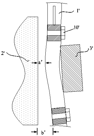
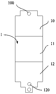
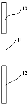
[0023] Such as figure 2 As shown, it shows a schematic front view of an embodiment of a new type of support block for a steam generator provided by the present invention; together with image 3 shown in the side view, and together with the Figure 4 and Figure 5 shown. In the present embodiment, the support block 1 is used to support the steam generator in the primary circuit of the nuclear power unit in a hot state; wherein:

[0024] The support pad 1 is a s...


PUM


Abstract

The invention discloses a novel supporting cushion block for a steam generator. The novel supporting cushion block is used for supporting the steam generator in a loop when a nuclear power unit is ina thermal state. The novel supporting cushion block is characterized in that the supporting cushion block is of a thin sheet structure, wherein fixing holes are formed in two ends of the supporting cushion block, a first surface of the supporting cushion block is in contact with a supporting body structure, and a certain gap is reserved between a second surface of the supporting cushion block anda side anchoring part; the supporting cushion block comprises a first section, a second section and a third section, wherein the first section and the second section are arranged at two ends of the supporting cushion block, the third section is arranged between the first section and the second section, and the thickness of the third section is smaller than the thickness of the first section and the thickness of the second section; and when the supporting cushion block is in the hot state, the third section is bent, and the maximum bending position does not exceed the planes of the first section and the second section towards the side anchoring part. By carrying out the novel supporting cushion block, the accuracy of the actual value and the measured value of the gap between the upper supporting cushion block and the side anchoring part of the steam generator can be improved, so that the secondary stress state of the loop during the thermal state of the unit is consistent with originaldesign, and therefore the reliability and the safety of the unit are improved.

Description

technical field [0001] The invention relates to the technical field of nuclear power plants. In particular it relates to a new type of support block for steam generators. Background technique [0002] The upper support block of the steam generator (the device that transfers the heat of the primary circuit of the nuclear power plant to the secondary circuit) is used to adjust the steam generator ring (used to fix the steam generator) and the side anchor (to limit the displacement of the steam generator) device) clearance device. In the prior art, it adopts equal thickness design. Provide proper clearance for the allowable displacement of the steam generator under normal operating conditions, limit the displacement of the steam generator and transfer the load of the steam generator to the side anchors under abnormal and accidental conditions (earthquake, primary circuit breach, etc.) . Every time the power plant unit is overhauled, the maintenance department of the power s...

Claims


Application Information

Patent Timeline
Patent Type & Authority Applications(China)
IPC IPC(8): F22B37/00
CPCF22B37/002
Inventor 孙江枫齐宇博李剑波翁文庆
Owner CHINA NUCLEAR POWER TECH RES INST CO LTD
Why Eureka
Try Eureka