High-performance upper-mounted butterfly valve

A high-performance, installed technology, applied in the direction of lift valve, valve details, valve device, etc., can solve the problems of inability to limit flow for a long time, and the valve is prone to water seepage.

Active Publication Date: 2018-05-29
ANHUI RONGDA VALVE
View PDF9 Cites 2 Cited by
  • Summary
  • Abstract
  • Description
  • Claims
  • Application Information

AI Technical Summary

Problems solved by technology

[0002] The valve is a control component in the pipeline fluid conveying system. It is used to change the channel section and the flow direction of the medium. Various valves, from the simplest cut-off valve to various valves used in extremely complex automatic control systems, but the existing valves are prone to water seepage during long-term use, or cannot achieve long-term flow limitation

Method used


Image

  • High-performance upper-mounted butterfly valve
  • High-performance upper-mounted butterfly valve
  • High-performance upper-mounted butterfly valve

Examples


Embodiment Construction

[0015] The following will clearly and completely describe the technical solutions in the embodiments of the present invention with reference to the accompanying drawings in the embodiments of the present invention. Obviously, the described embodiments are only some, not all, embodiments of the present invention. Based on the embodiments of the present invention, all other embodiments obtained by persons of ordinary skill in the art without making creative efforts belong to the protection scope of the present invention.

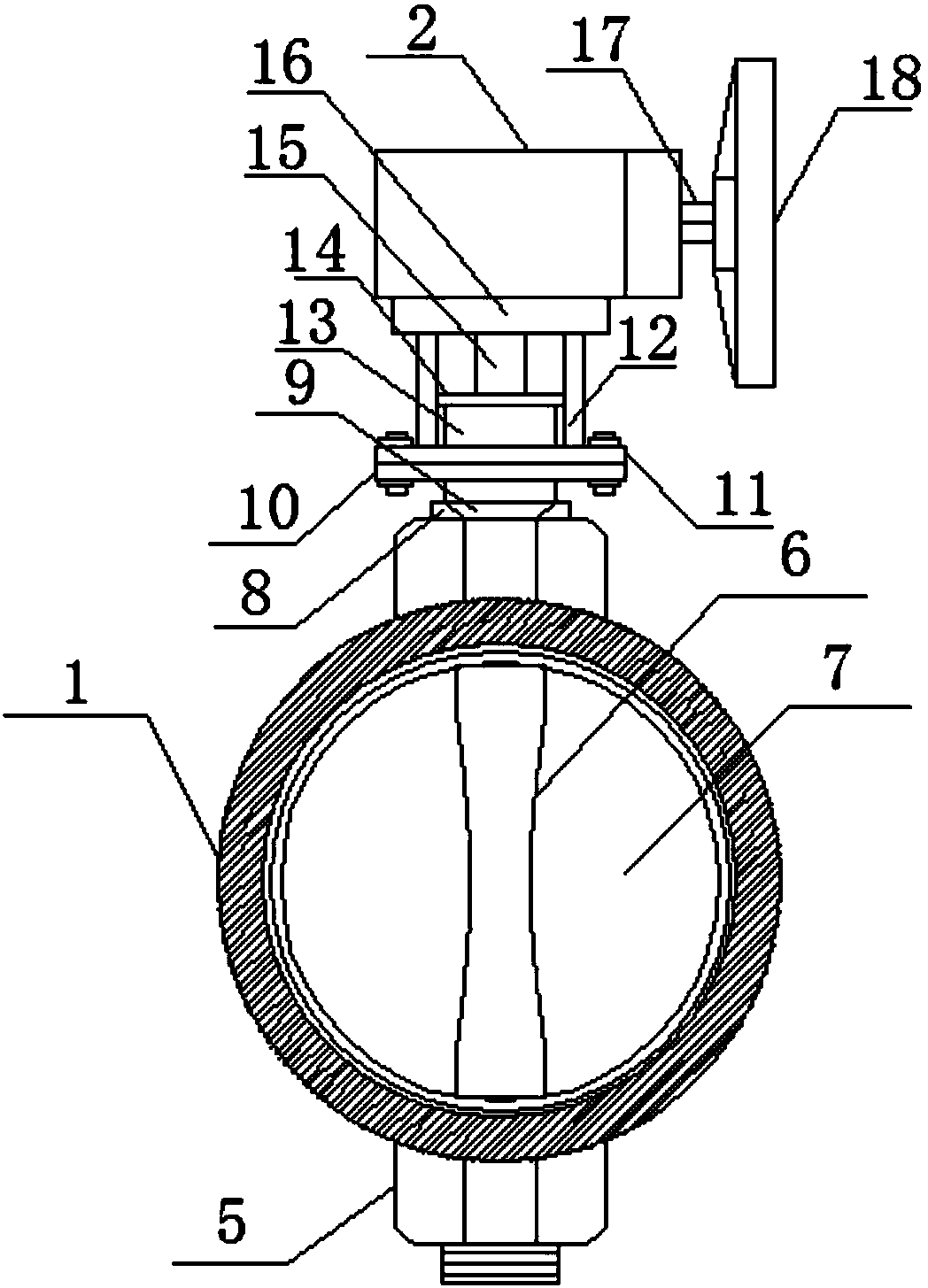
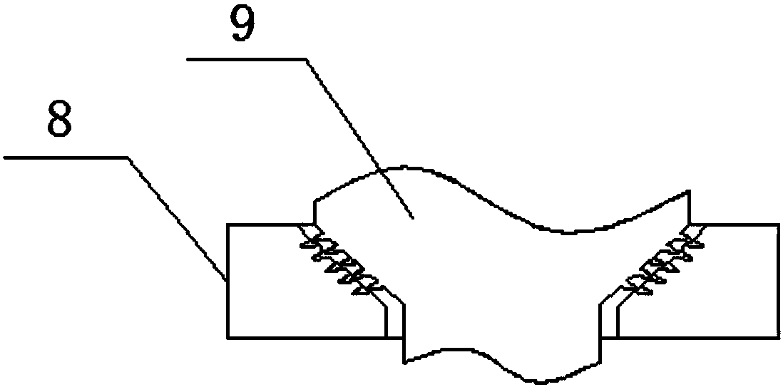
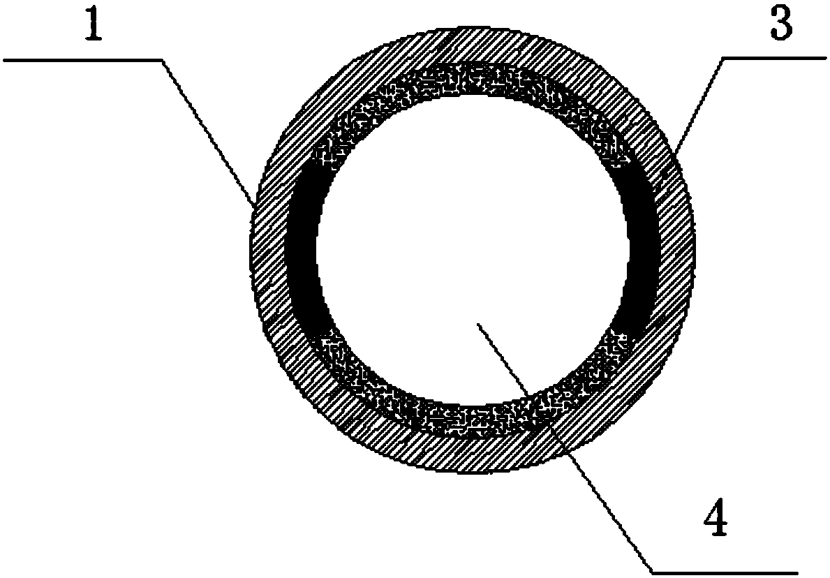
[0016] The present invention provides such Figure 1-3 A high-performance top-mounted butterfly valve shown includes a butterfly valve casing 1 and a box body 2. The box body 2 is arranged on the top of the butterfly valve casing 1, and the butterfly valve casing 1 is provided with a limit block 3 and a water tank 4. Through the limit The setting of the block 3 is conducive to providing support for the flow limiting plate 7, preventing the impact of the flow l...


PUM


Abstract

The invention discloses a high-performance upper-mounted butterfly valve which comprises a butterfly valve shell and a box body. The box body is arranged at the top end of the butterfly valve shell. Limiting blocks and a water tank are arranged in the butterfly valve shell. One side of each limiting block is fixedly connected with the inner wall of the butterfly valve shell. Fixed shafts are arranged at the upper end and the lower end of the butterfly valve shell. A rotating shaft is arranged in the butterfly valve shell, and the rotating shaft penetrates the butterfly valve shell and extendsinto the fixed shafts. The rotating shaft and the fixed shafts are movably connected. Flow limiting plates are arranged on the two sides of the rotating shaft and are arranged in the butterfly valve shell. A screw groove column is arranged at the top end of the upper fixed shaft. According to the high-performance upper-mounted butterfly valve, through the arrangement of the limiting blocks, supporting force can be provided for the flow limiting plates easily, and the situation that when the medium flowing speed is too high, the flow limiting plates are impacted to rotate, and consequently thefunction of cutting off media cannot be achieved is avoided; and through the arrangement of a vibration reduction plate, vibration generated when acting force is transmitted can be reduced easily, damage caused by vibration to equipment is avoided, and therefore the aim of the high-performance upper-mounted butterfly valve is achieved.

Description

technical field [0001] The invention relates to the technical field of valves, in particular to a high-performance top-mounted butterfly valve. Background technique [0002] The valve is a control component in the pipeline fluid delivery system. It is used to change the channel section and the flow direction of the medium. Various valves, from the simplest cut-off valve to various valves used in extremely complex automatic control systems, but the existing valves are prone to water seepage during long-term use, or cannot achieve long-term flow restriction. Therefore, it is necessary to invent a high-performance top entry butterfly valve to solve the above problems. Contents of the invention [0003] The purpose of the present invention is to provide a high-performance top entry butterfly valve to solve the problems raised in the above background technology. [0004] In order to achieve the above object, the present invention provides the following technical solutions: a ...

Claims


Application Information

Patent Timeline
Patent Type & Authority Applications(China)
IPC IPC(8): F16K1/22F16K27/02F16F15/10
CPCF16F15/10F16F2232/02F16K1/22F16K27/0218
Inventor 胡启明
Owner ANHUI RONGDA VALVE
Why Eureka
Try Eureka