Automatic clamping device

A power and power shaft technology, applied in the field of automatic clamping devices, can solve the problems of unreliable grasping of materials by the manipulator, complicated production and processing, and long design cycle, etc., to achieve wide practicability and promotion value, low cost, and good maneuverability Effect

Inactive Publication Date: 2018-05-29
PIONEDA INTELLIGENT AUTOMATION TECH NINGBO
View PDF0 Cites 4 Cited by
  • Summary
  • Abstract
  • Description
  • Claims
  • Application Information

AI Technical Summary

Problems solved by technology

[0002] In the process of industrial automation production, manipulators are needed in many places. Most of the solutions are realized by using cylinders supplemented by corresponding fixtures. The structure is more

Method used


Image

  • Automatic clamping device
  • Automatic clamping device
  • Automatic clamping device

Examples


Embodiment Construction

[0016] The present invention will be further described below in conjunction with the accompanying drawings.

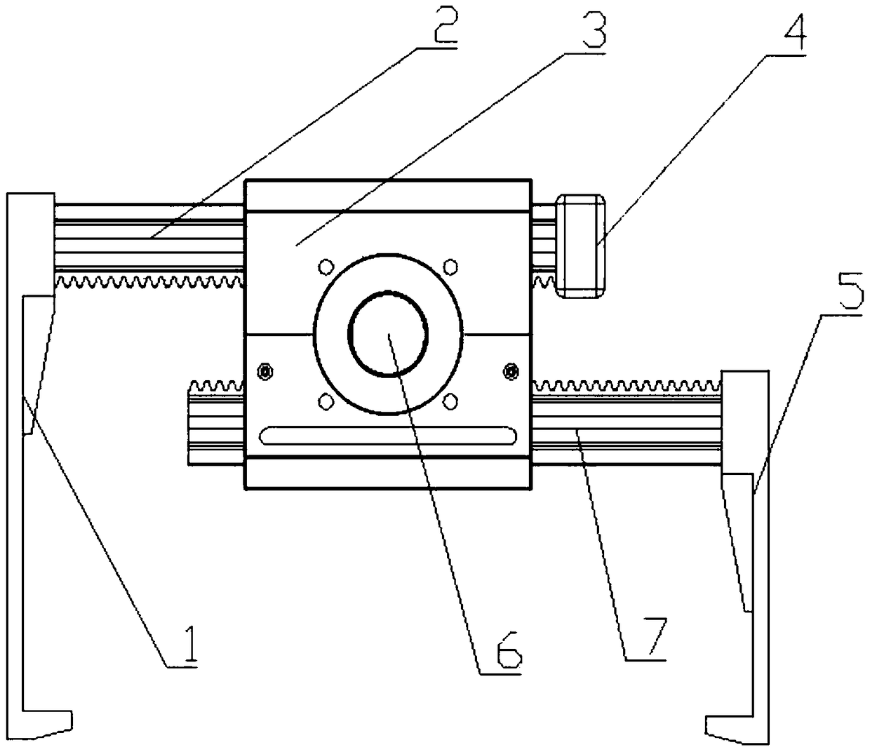
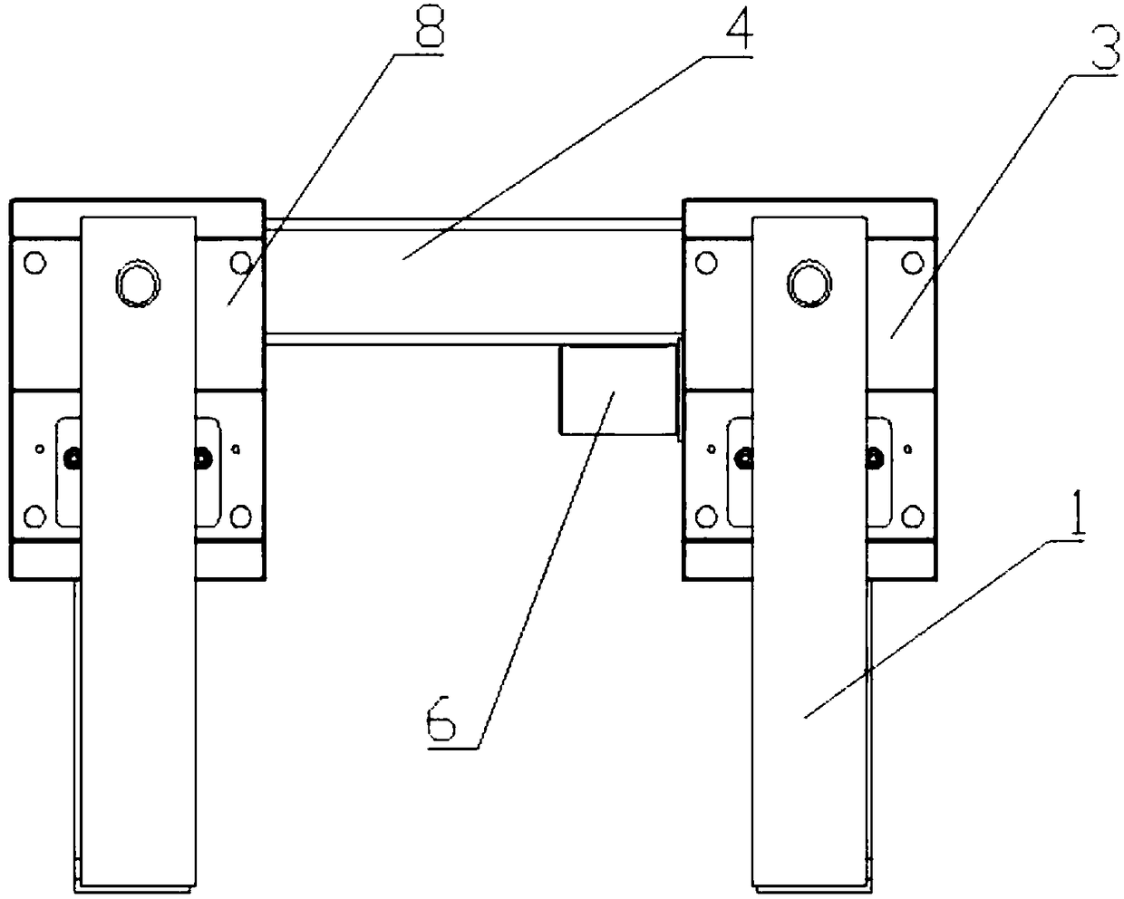
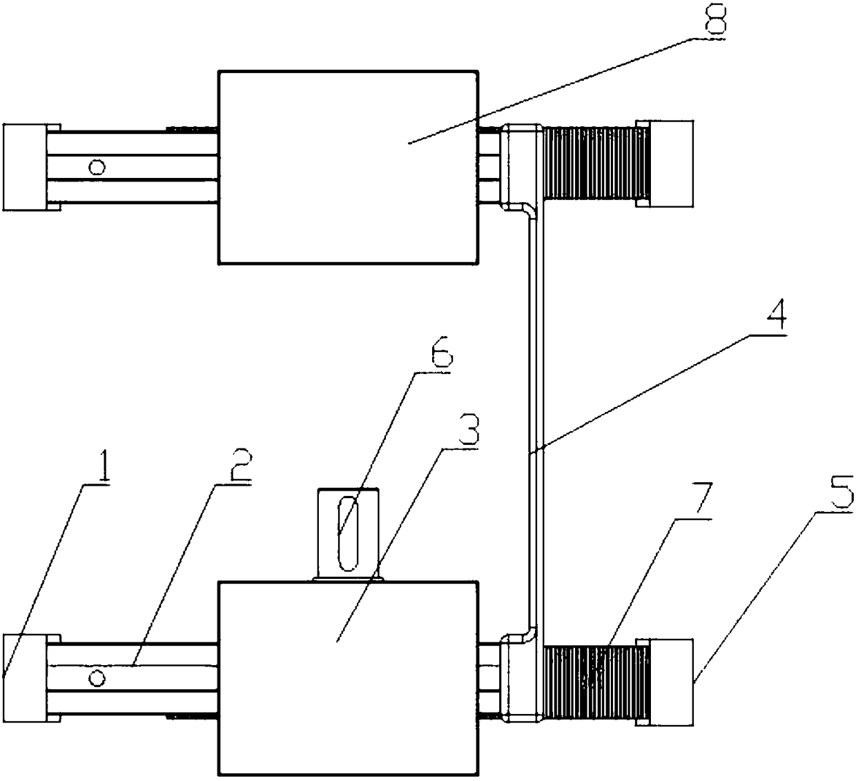
[0017] The present invention includes a power automation module 3, a driven automation module 8 and a connecting plate 4. The power automation module 3 includes a power shaft 6, a housing, a guide rail rack I2 and a guide rail rack II7, and two vertically opposite sides of the housing A mounting hole for the power shaft 6 is provided, bearings are arranged at both ends of the power shaft 6, and the bearings are installed on the power shaft mounting hole, one end of the power shaft 6 is arranged on the outside of the housing, and a There are gears, the guide rail rack I2 and the guide rail rack II7 vertically pass through the two vertical sides of the housing parallel to the power shaft 6, the tooth surfaces of the guide rail rack I2 and the guide rail rack II7 are opposite, and mesh with the gears respectively, and The forward direction of the two rail racks is opposit...


PUM


Abstract

The invention aims to provide an automatic clamping device. The clamping device is characterized in that a power automation module comprises a power shaft, a shell, a guide rail rack I and a guide rail rack II, the two vertical opposite side faces of the shell are provided with mounting holes of the power shaft, and bearings are arranged at the two ends of the power shaft; the bearings are arranged on the mounting holes of the power shaft, and one end of the power shaft is arranged outside the shell; a gear is arranged on the power shaft and located in the shell, the guide rail rack I and theguide rail rack II perpendicularly penetrate through two shell vertical side faces which are parallel to the power shaft, the tooth surfaces of the guide rail racks are opposite to each other and advance in opposite directions, and the guide rail racks are meshed with the gear in a cooperating mode; and a mechanical claw I is fixedly connected to one end of the guide rail rack I, a mechanical clawII is arranged at one end, which is symmetric with the guide rail rack I, of the guide rail rack II, the other end of the guide rail rack I is fixedly connected with a connecting plate, and the otherend of the connecting plate is fixedly connected with a driven automation module; and the power automation module and the driven automation module are in parallel position relation. The automatic clamping device is simple in structure and easy to realize.

Description

technical field [0001] The invention relates to a manipulator for material clamping, in particular to an automatic clamping device. Background technique [0002] In the process of industrial automation production, manipulators are needed in many places. Most of the solutions are realized by using cylinders supplemented by corresponding fixtures. The structure is more complicated, the design cycle is longer, the production and processing are complicated, and the installation is cumbersome. , low accuracy, low efficiency, and the manipulator is not reliable in grabbing materials. Contents of the invention [0003] The object of the present invention is to provide an automatic clamping device with simple structure, convenient operation, high accuracy and high efficiency. [0004] In order to achieve the above object, the technical solution adopted in the present invention is: an automatic clamping device, including a power automation module, a driven automation module and a ...

Claims


Application Information

Patent Timeline
IPC IPC(8): B25J15/08
CPCB25J15/08
Inventor 张新鹏
Owner PIONEDA INTELLIGENT AUTOMATION TECH NINGBO
Why Eureka
Try Eureka