A vacuum pump cleaning equipment

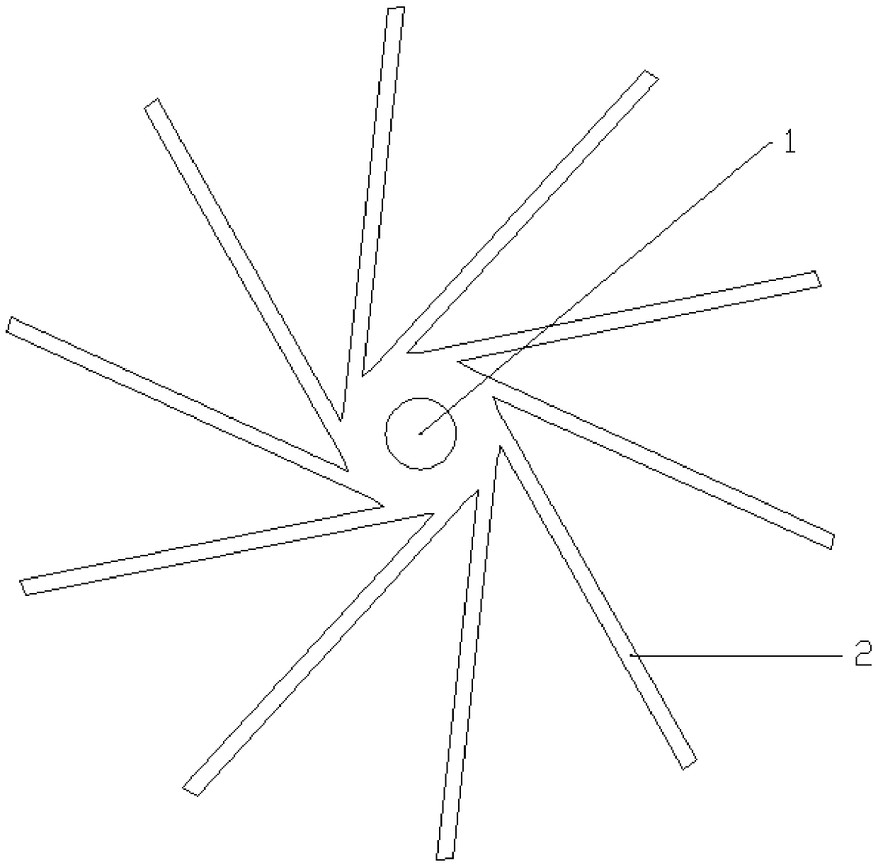
A technology for vacuum pumps and equipment, which is applied in the field of vacuum pump cleaning equipment, and can solve problems such as difficult wiping and insufficient cleaning of blades 2

Active Publication Date: 2019-12-31
济宁中再生华惠医药科技有限公司
View PDF1 Cites 0 Cited by
  • Summary
  • Abstract
  • Description
  • Claims
  • Application Information

AI Technical Summary

Problems solved by technology

[0003] Therefore, when maintaining the water ring vacuum pump, the water ring vacuum pump is generally disassembled, such as figure 1 For the impeller shown in , hold the shaft 1 of the impeller and wipe the dirt on the blade 2; however, the blade 2 of the impeller is generally arc-shaped, and it is difficult to wipe the position of the blade 2 close to the shaft 1 when wiping , it is easy to cause the local cleaning of blade 2 to be insufficient

Method used


Image

  • A vacuum pump cleaning equipment
  • A vacuum pump cleaning equipment
  • A vacuum pump cleaning equipment

Examples


Embodiment Construction

[0018] Further detailed explanation through specific implementation mode below:

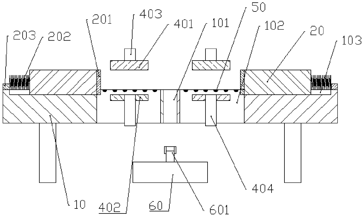
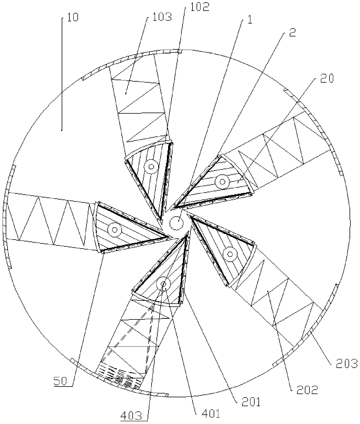
[0019] The reference signs in the drawings of the description include: shaft part 1, blade 2, cleaning table 10, vertical through hole 101, vertical chute 102, horizontal chute 103, cleaning block 20, cleaning brush 201, compression spring 202, Electromagnet 203 , upper pressing plate 401 , lower pressing plate 402 , first connecting rod 403 , second connecting rod 404 , contact sensor 50 , motor 60 , rotating shaft 601 .

[0020] The embodiment is basically as attached figure 2 And attached image 3 Shown: a vacuum pump cleaning equipment, including a disc-shaped cleaning table 10, four cleaning units, four moving units and four induction units, the center of the cleaning table 10 is provided with a vertical through hole for the shaft to pass through 101.

[0021] The cleaning unit comprises a cleaning block 20, a stage clip 202 arranged horizontally and an electromagnet 203 that attracts th...


PUM


Abstract

The invention relates to the field of cleaning devices, and in particular, discloses vacuum pump cleaning equipment. The vacuum pump cleaning equipment is provided with a cleaning unit and a moving unit; the moving unit can drive a cleaning block in the cleaning unit to move up and down; to conveniently wipe and clean the side surfaces of blades; and the shape of a cross section of the cleaning block is consistent with the shapes of fan-shaped surfaces formed between the blades, so that cleaning brushes on the side walls of the cleaning block can be fully contacted with the side walls of the blades, the positions, near shaft parts, of the blades are comprehensively wiped, and comprehensive cleaning of the blades is realized.

Description

technical field [0001] The invention belongs to the field of cleaning devices, and in particular relates to vacuum pump cleaning equipment. Background technique [0002] The water ring vacuum pump is a kind of rough vacuum pump, which realizes suction, compression and exhaust by changing the volume of the pump chamber, so it belongs to the variable capacity vacuum pump. A water ring vacuum pump is generally composed of an impeller, a pump body, a suction and exhaust disc, a water ring formed by water on the inner wall of the pump body, a suction port, an exhaust port, and an auxiliary exhaust valve. When vacuuming other containers, the air is inhaled from the air inlet of the vacuum pump, and then enters between the water ring and the blades of the impeller. Part of the impurities in the air will enter the water, and some will accumulate on the blades. When the water ring vacuum pump is stationary, the impurities in the water will adhere to the blades, causing the air volum...

Claims


Application Information

Patent Timeline
Patent Type & Authority Patents(China)
IPC IPC(8): B08B1/02
CPCB08B1/002B08B1/006B08B1/02
Inventor 郑文忠
Owner 济宁中再生华惠医药科技有限公司
Why Eureka
Try Eureka