
Rotating electrical machine

A technology of rotating motors and rotating shafts, applied in electromechanical devices, electrical components, electric components, etc., can solve problems such as demagnetization of permanent magnets, deterioration of parts, etc., and achieve the effect of maintaining and improving detection accuracy

Inactive Publication Date: 2018-05-25
TOYOTA JIDOSHA KK
View PDF7 Cites 3 Cited by
  • Summary
  • Abstract
  • Description
  • Claims
  • Application Information

AI Technical Summary

Problems solved by technology

If the rotating electrical machine becomes too hot due to the above-mentioned heat generation, it will cause deterioration of parts, demagnetization of permanent magnets, etc.

Method used


Image

  • Rotating electrical machine
  • Rotating electrical machine
  • Rotating electrical machine

Examples


Embodiment Construction

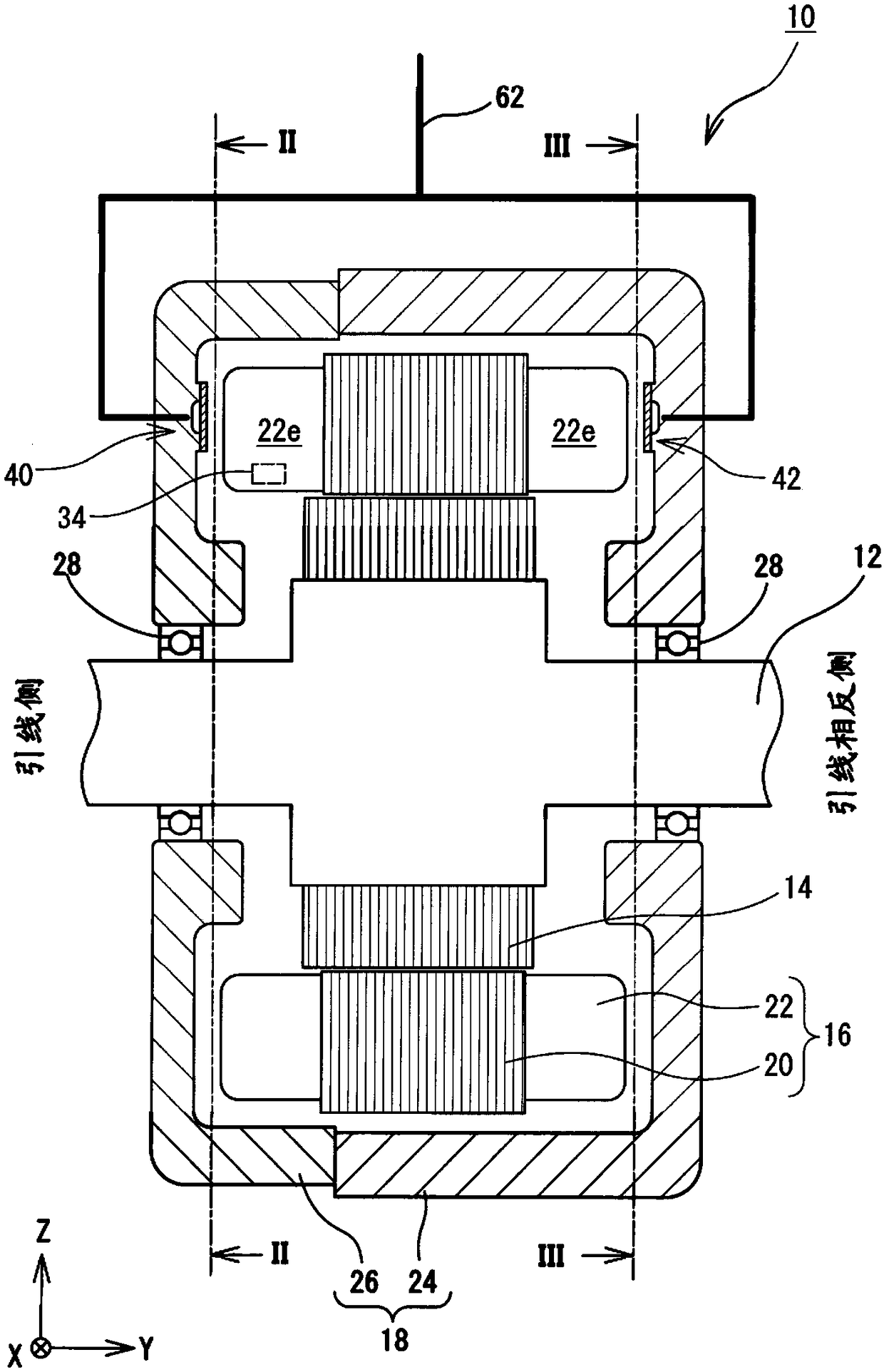
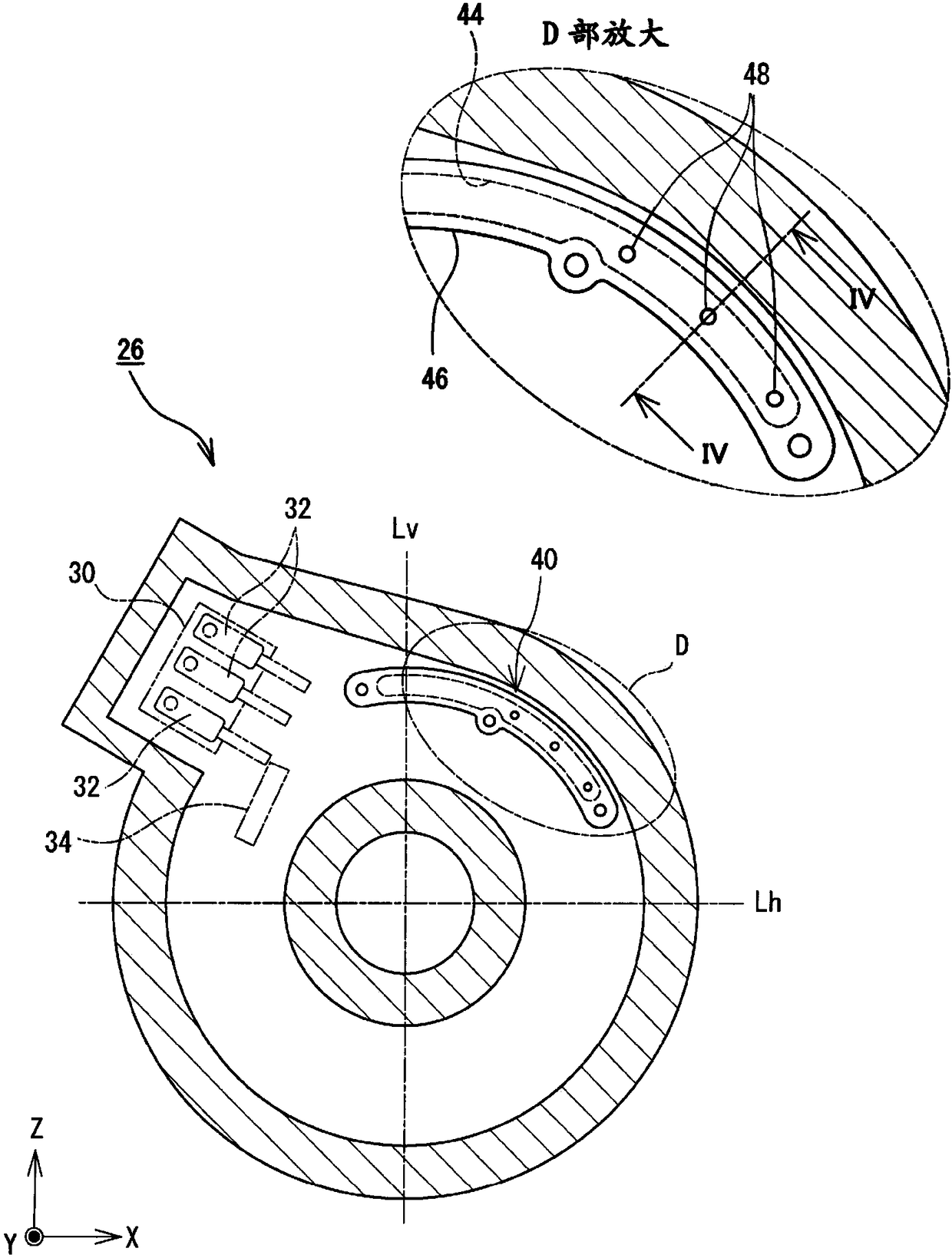
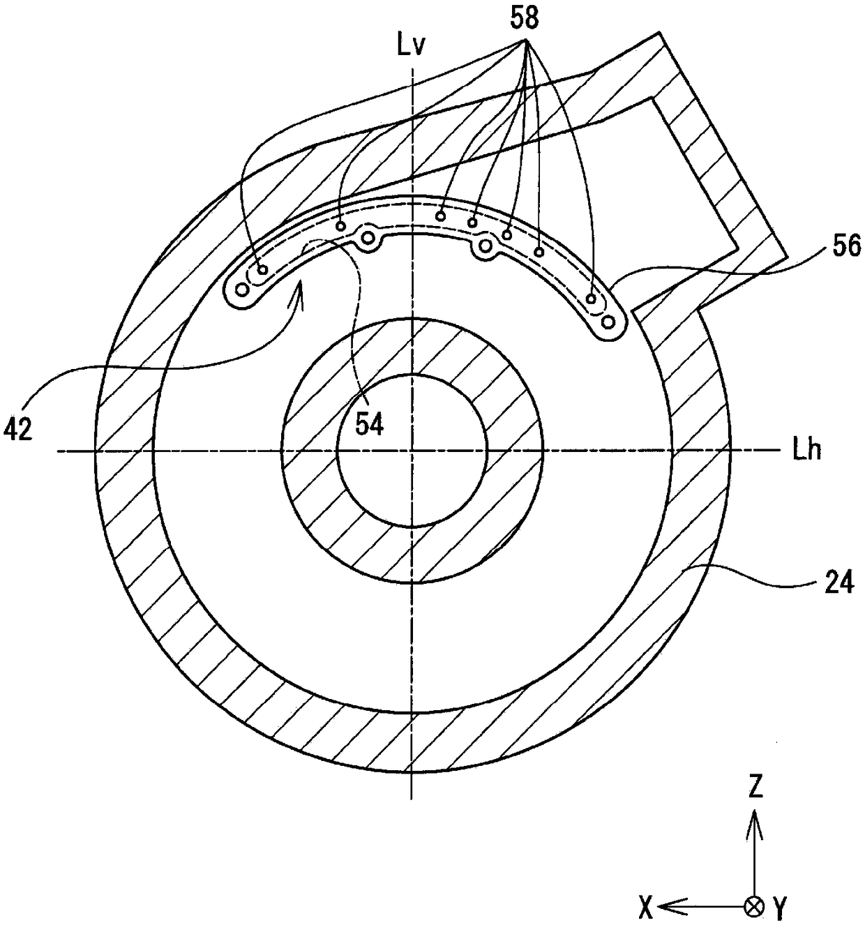
[0036] Hereinafter, a rotating electrical machine 10 as an embodiment will be described with reference to the drawings. figure 1 It is a schematic longitudinal sectional view of the rotating electric machine 10 as an embodiment. in addition, figure 2 yes figure 1 The II-II sectional view of image 3 yes figure 1 Sectional view of III-III. in addition, Figure 4 yes figure 2 Sectional view of IV-IV. In addition, in Figure 1 ~ Figure 3 , gravity acts from above to below the paper surface, the Z-axis direction is the gravity direction, and the X-axis and Y-axis directions are horizontal directions.

[0037] The rotating electric machine 10 described above is mounted on an electric vehicle such as a hybrid vehicle or an electric vehicle. In an electric vehicle, the rotating electrical machine 10 may be used as a running motor that generates power for running the vehicle, or as a generator that generates power by regenerative braking force or surplus power of an engine....


PUM


Abstract

The invention relates to a rotating electrical machine. A cooling structure for a rotating electrical machine includes a rotating electrical machine, a temperature sensor, and a first discharge mechanism. A plurality of discharge holes of the first discharge mechanism is disposed in a region excluding an avoidance region. The avoidance region is the same region as an arrangement region that is oneof a right side region and a left side region with respect to a vertical line passing an axis of the stator as seen in the axial direction of the stator core, the one of the right side region and theleft side region being a region in which the temperature sensor is arranged and the avoidance region is located above a lower end of the temperature sensor in the gravitation direction.

Description

technical field [0001] The present invention relates to a rotating electrical machine, which is placed with a rotating shaft intersecting the direction of gravity, and a temperature sensor is attached to a coil end protruding axially outward from an end surface on one end side of a stator core in the axial direction. For example, the rotating electric machine of the present invention is mounted on a vehicle as an electric motor for driving the vehicle. Background technique [0002] As is well known, a rotating electrical machine generates losses such as copper loss, iron loss, and mechanical loss as it is driven, and generates heat corresponding to the above losses. If the rotating electric machine becomes too hot due to the above-mentioned heat generation, deterioration of components, demagnetization of permanent magnets, and the like will be incurred. Then, in the related art, a technique has been proposed to cool the stator coil and thus the rotary electric machine by in...

Claims


Application Information

Patent Timeline
Patent Type & Authority Applications(China)
IPC IPC(8): H02K11/25H02K9/00
CPCH02K11/25H02K9/00H02K5/203H02K9/19H02K9/193H02K2205/09H02K2213/03
Inventor 山岸义忠今川圣
Owner TOYOTA JIDOSHA KK
Learn More