
Patsnap Eureka
For R&D, Patsnap Eureka makes reading and utilizing patents & technical documents easy.
Patsnap Eureka AIR
Designed for self-driven R&D workflows. Generate viable solutions, solve complex R&D challenges, empower your innovation with AI.

Patsnap Eureka Materials
Designed for material experts only. Revolutionize your material R&D, from search, analyze, to developing new materials.

TechResearch
Generate reliable direction feasibility study reports for your R&D in just a few steps.

TechSeek
Discover and master advanced knowledge NOW. Basics, ideas, possibilities, all at once.

TechMind
As an expert in R&D Theories, TechMind can generates customized viable solutions instantly.

TechRisk
Analyze your overall solution with one click, know your potential R&D risks in advance.

TechMonitor
Get weekly tech updates, stay abreast of the latest tech innovations and key insights.
A two-way toll collector for expressways
A technology of expressways and toll collectors, applied in the field of infrastructure, can solve problems such as waste of human resources, inconvenience for car owners, and unfavorable vehicles passing quickly, and achieve the effects of convenient operation, improved card reading efficiency, and simple structure
- Summary
- Abstract
- Description
- Claims
- Application Information
AI Technical Summary
Problems solved by technology
Method used
Image

Examples
Embodiment 1
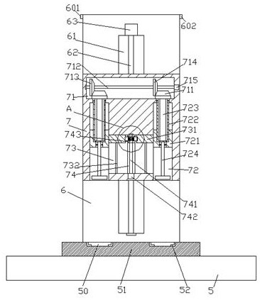
[0033] When dual card readers are required to read cards at the same time, the billing card is first placed between the clamping devices 52, and then the second motor 742 drives the first screw 741 to rotate, so that the first screw 741 drives the pusher 743 to gradually move along the first screw 743. The three chute 74 slides in the downward direction, because the locking heads 7433 on the left and right sides protrude out of the left and right sides of the pushing device 743 respectively and are fully inserted into the locking grooves 7311 in the pushing sliders 731 on the left and right sides to the greatest extent, so that the pushing When the device 743 slides down, it drives the sliders 721 on the left and right sides to gradually slide downwards along the second chute 72 on the left and right sides respectively. Outer spline rotating rod 723 outer surfaces slide down gradually, until such as Figure 4 The push sliders 731 on the left and right sides shown move to the b...
Embodiment 2
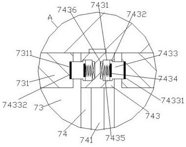
[0035] When the left card reader is required to read the card, the billing card is first put between the clamping devices 52, and then the inductive wire device 7436 in the locking cavity 7431 on the right is powered on, so that the inductive wire device 7436 is connected to the right side The magnet 7434 in the locking head 7433 produces suction force. At this time, the right locking head 7433 overcomes the force of the spring coil 7435 between the right induction wire device 7436 and the right magnet 7434 and moves toward the right induction wire device. Make the right side locking head 7433 completely break away from the locking groove 7311 in the right side push slider 731, and then drive the first screw rod 741 to rotate through the second motor 742, so that the first screw rod 741 drives the pushing device 743 to gradually move along the third chute 74 slides downward, so that the pusher 743 slides downward and drives the slider 721 on the left to gradually slide downward...
Embodiment 3
[0037] When the right card reader is required to read the card, the billing card is first put between the clamping devices 52, and then the inductive wire device 7436 in the locking cavity 7431 on the left side is powered on, so that the inductive wire device 7436 is connected to the left side The magnet 7434 in the locking head 7433 generates an attractive force. At this time, the left locking head 7433 overcomes the force of the spring coil 7435 between the left induction wire device 7436 and the left magnet 7434 and moves toward the left induction wire device. Make the left locking head 7433 completely break away from the locking groove 7311 in the left push slider 731, and then drive the first screw 741 to rotate through the second motor 742, so that the first screw 741 drives the pushing device 743 to gradually move along the third chute 74 slides downward, so that the pusher 743 slides downward and drives the slide block 721 on the right to gradually slide downward along ...
PUM
 Abstract
Description
Claims
Application Information
 - R&D Engineer
- R&D Manager
- IP Professional
- Industry Leading Data Capabilities
- Powerful AI technology
- Patent DNA Extraction
Browse by: Latest US Patents, China's latest patents, Technical Efficacy Thesaurus, Application Domain, Technology Topic, Popular Technical Reports.
© 2024 PatSnap. All rights reserved.Legal|Privacy policy|Modern Slavery Act Transparency Statement|Sitemap|About US| Contact US: help@patsnap.com