U tube

A technology of hairpin tube and tube body, which is applied to tubular elements, evaporators/condensers, lighting and heating equipment, etc., can solve the problems of loose sealing of U-shaped hairpin tubes, achieve simple structure, solve the problem of poor sealing and design clever effect

Inactive Publication Date: 2018-05-25
TIANJIN LONGTAI HEATING & COOLING EQUIP MFG
View PDF0 Cites 0 Cited by
  • Summary
  • Abstract
  • Description
  • Claims
  • Application Information

AI Technical Summary

Problems solved by technology

However, in actual production, the connection between the U-shaped hairpin tube and the warped fin is often not tightly sealed.

Method used


Image

  • U tube

Examples


Embodiment Construction

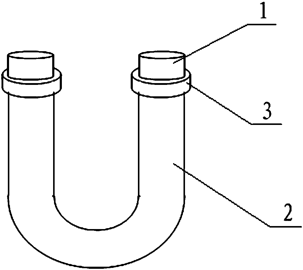
[0011] In order to further illustrate the present invention, the accompanying drawings are now described in detail:

[0012] like figure 1 As shown, the hairpin tube includes a tube body, the cross section of the tube body is a circle, the longitudinal section is a U-shaped structure, the tube body is a double-layer structure, and the length of the outer tube body 2 is shorter than that of the inner layer In the pipe body 1, the outer layer pipe body is sealed with the inner layer pipe body at its port, and the outer layer pipe body also has an outer flange 3 (which may also be a groove) structure at the port.

[0013] The above are only the preferred embodiments of the present invention. It should be pointed out that for those skilled in the art, without departing from the principles of the present invention, several improvements and modifications can be made. It should be regarded as the protection scope of the present invention.


PUM


Abstract

The invention provides a U tube. A tube body is included, the tube body is of a dual-layer structure, the length of the outer-layer tube body is smaller than that of the inner-layer tube body, the outer-layer tube body and the inner-layer tube body are sealed on a port of the outer-layer tube body, a groove or outer-turning-side structure is arranged on the port of the outer-layer tube body. The Utube is simple in structure and ingenious in design, the problem that the U tube and warping fins are not tight in seal is solved effectively, and the tube is suitable for large-scale industrial production needs.

Description

technical field [0001] The invention relates to a condensing device, in particular to a hairpin tube. Background technique [0002] At present, the air-conditioning condenser generally includes several U-shaped hairpin tubes. The outer wall of the U-shaped hairpin tube is equipped with warped fins. The warped fins connect the U-shaped hairpin tube into one. The U-shaped hairpin tube is divided into inner and outer rows and fixed on the warp. In the fin, each interface of the U-shaped hairpin tube is respectively connected with a refrigerant input pipe, a refrigerant output pipe and a connecting pipe for the refrigerant to form a circulation in the U-shaped hairpin pipe. The number of U-shaped hairpin tubes is less than the number of U-shaped hairpin tubes in the outer row, and the connecting pipe between the U-shaped hairpin tubes in the inner row and the U-shaped hairpin tubes in the outer row includes a tee elbow. However, in actual production, the connection between the ...

Claims


Application Information

Patent Timeline
Patent Type & Authority Applications(China)
IPC IPC(8): F28F1/00F25B39/04
CPCF28F1/003F25B39/04
Inventor 孙鹏
Owner TIANJIN LONGTAI HEATING & COOLING EQUIP MFG
Why Eureka
Try Eureka