A method of processing a compressor impeller

A processing method and compressor technology, which are applied to metal processing equipment, metal processing mechanical parts, manufacturing tools, etc., can solve the problem of large outer diameter of the wheel surface of the compressor impeller, and achieve simple structure, convenient installation, and guaranteed processing accuracy. and the effect of balancing precision

Active Publication Date: 2019-09-10
凤城太平洋神龙增压器有限公司
View PDF7 Cites 0 Cited by
  • Summary
  • Abstract
  • Description
  • Claims
  • Application Information

AI Technical Summary

Problems solved by technology

[0002] In the prior art, when processing the compressor impeller, such as Figure 6~7 As shown, the outer circle of the compressor impeller is first held by the three claws, and the front end of the three claws is against the outer limit of the wheel surface, then the inner hole is processed on the back of the wheel, and then the bed is inserted into the compressor impeller using the expansion shaft The compressor impeller is fixed in the inner hole, and the R end face and the shaft end face are fixed. In this way, the three-claw front end is used to resist the outer edge of the wheel face, and the outer circle of the compressor impeller face is larger, so the machining accuracy and balance accuracy still needs to be improved

Method used


Image

  • A method of processing a compressor impeller
  • A method of processing a compressor impeller
  • A method of processing a compressor impeller

Examples


Embodiment Construction

[0032] The present invention will be described in further detail below in conjunction with the accompanying drawings.

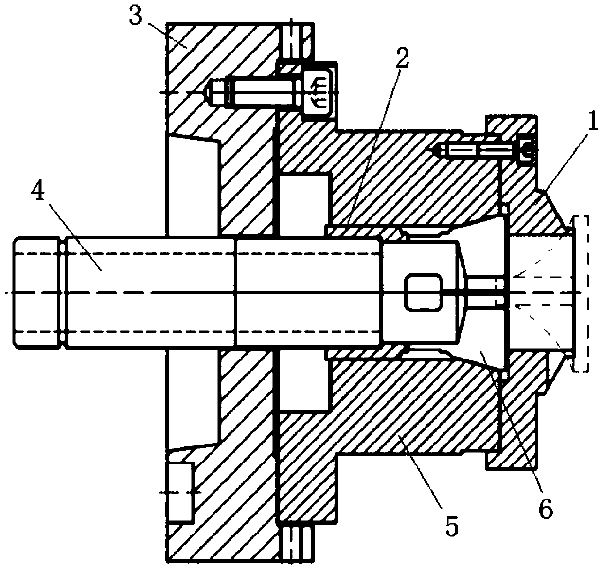
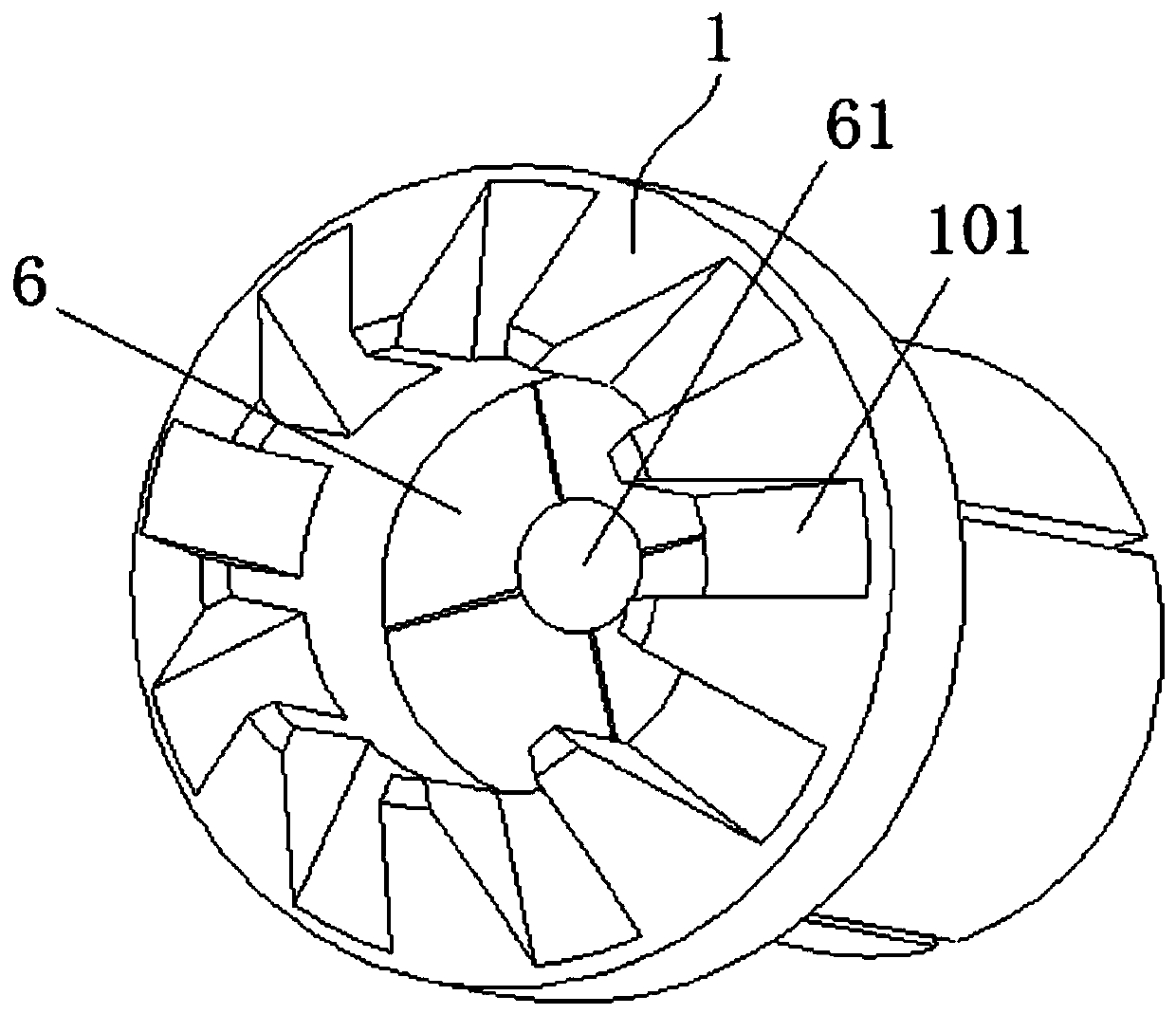
[0033] Such as figure 1 and image 3 As shown, the first fixture tool used in the present invention includes a block 3, a drive shaft 4, a mounting sleeve 5, an expansion block 6 and a limit cover 1, wherein the drive shaft 4 is connected with the hydraulic pull rod on the machine tool spindle, and the The clamping block 3 is provided with a notch groove and the end face of the main shaft of the machine tool to form a notch fit limit, and is fixed on the main shaft by screws. The installation sleeve 5 is fixed on the block 3 by screws, the limit cover 1 is installed on the free end of the installation sleeve 5 by screws, and a plurality of expansion blocks 6 are arranged inside the free end of the installation sleeve 5 , and the drive shaft 4 passes through the clamp block 3 and the installation sleeve 5 and is connected to each expansion block 6, and a sl...


PUM


Abstract

The invention relates to the field of compressor impeller manufacturing, in particular to a machining method of a compressor impeller. The machining method of the compressor impeller comprises the following steps that 1, the compressor impeller is arranged on a machine tool provided with a first clamp tooling, and the front shaft end of the compressor impeller stretches into a clamping hole of thefirst clamp tooling; 2, an expansion block of the first clamp tooling shrinks to clamp the front shaft end of the compressor impeller, and a root portion of the wheel face of the compressor impellerabuts against the end face of a free end of a limiting cover; 3, wheel back of the compressor impeller and an outer circle of the compressor impeller are machined, and a tool is changed to machine theinner hole of the compressor impeller; 4, a workpiece in step 3 is unloaded and arranged on the machine tool provided with a second clamp tooling, and the wheel back of the compressor impeller abutsagainst any seam allowance face located at the circular edge of a clamping hole of the second clamp tooling; 5, a clamping block of the second clamp tooling shrinks to fix the workpiece, and a front end roof pillar of a connecting shaft of the second clamp tooling abuts against the wheel back of the compressor impeller; and 6, a R end face of the compressor impeller and the end face of the front shaft end are machined. The machining method of the compressor impeller can effectively guarantee the accuracy of subsequent balance.

Description

technical field [0001] The invention relates to the production field of a compressor impeller supercharger, in particular to a processing method of an air compressor impeller. Background technique [0002] In the prior art, when processing the compressor impeller, such as Figure 6~7 As shown, the outer circle of the compressor impeller is first held by the three claws, and the front end of the three claws is against the outer limit of the wheel surface, then the inner hole is processed on the back of the wheel, and then the bed is inserted into the compressor impeller using the expansion shaft The compressor impeller is fixed in the inner hole, and the R end face and the shaft end face are fixed. In this way, the three-claw front end is used to resist the outer edge of the wheel face, and the outer circle of the compressor impeller face is larger, so the machining accuracy and balance accuracy There is still room for improvement. Contents of the invention [0003] The pu...

Claims


Application Information

Patent Timeline
Patent Type & Authority Patents(China)
IPC IPC(8): B23B5/00B23Q3/12
Inventor 刘济豪赵明伟
Owner 凤城太平洋神龙增压器有限公司
Why Eureka
Try Eureka