Gas-liquid separation equipment facilitating gas concentration testing

A gas-liquid separation and gas concentration technology, which is applied in separation methods, liquid degassing, and liquid degassing through filtration, can solve the problems of affecting the detection efficiency of gas concentration in liquids, cumbersome separation process, complex structure, etc., and is easy to realize , improve the filtration efficiency, and the overall structure is simple

Inactive Publication Date: 2018-05-25
曾国春
View PDF0 Cites 0 Cited by
  • Summary
  • Abstract
  • Description
  • Claims
  • Application Information

AI Technical Summary

Problems solved by technology

[0002] In industrial construction, it is often necessary to detect the gas concentration in the liquid. When detecting the gas content in the liquid, it is often necessary to separate the gas in the liquid. The existing equipment for separating the gas in the liquid generally has complex structures, cumbersome separation processes, and Facilitate the detection of defects in separated gases, which affect the efficiency of detecting gas concentrations in liquids

Method used


Image

  • Gas-liquid separation equipment facilitating gas concentration testing
  • Gas-liquid separation equipment facilitating gas concentration testing

Examples


Embodiment

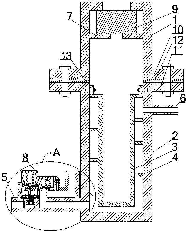
[0021] Such as figure 1 and figure 2 As shown, the gas-liquid separation equipment that is convenient for testing the gas concentration includes an upper shell 1, a lower shell 2 and a gas-liquid filter diaphragm 3, wherein the upper shell 1 forms a drum shape with an open lower end, and the lower shell 2 forms an upper end. Open barrel shape, the upper end of the lower housing 2 is sealed and connected with the lower end of the upper housing 1 , the gas-liquid filter membrane 3 is arranged in the lower housing 2 , and its upper end is sealed and connected with the inner wall of the lower housing 2 . A gas cavity is formed between the upper shell 1, the lower shell 2, and the gas-liquid filter diaphragm 3, and a transition chamber is formed between the lower shell 2 and the gas-liquid filter diaphragm 3. The upper and lower sides of the lower shell 2 A liquid outlet pipe 6 and a liquid inlet pipe 5 are respectively arranged on the wall, and both the liquid outlet pipe 6 and ...


PUM

PropertyMeasurementUnit
pore sizeaaaaaaaaaa

Abstract

The invention discloses gas-liquid separation equipment facilitating gas concentration testing. The gas-liquid separation equipment comprises an upper casing, a lower casing and a gas-liquid filtration diaphragm which constitute a gas accommodating cavity, a transition cavity is formed between the lower casing and the gas-liquid filtration diaphragm, a liquid inlet pipe and a liquid outlet pipe which are communicated with the transition cavity are arranged on the side wall of the lower casing, a control assembly is arranged on the liquid inlet pipe, the control assembly comprises a pressure limiting assembly arranged on a pipeline between a liquid inlet and a liquid inlet as well as a pressure relief assembly arranged on a channel connecting the liquid outlet and a liquid drain port in the pressure limiting assembly. Spiral isolation plates wind around the outer side wall of the gas-liquid filtration diaphragm and divide the transition cavity to form spiral channels communicated withthe liquid inlet pipe and the liquid outlet pipe. The gas-liquid separation equipment can avoid damage to inner assemblies and is convenient to operate and high in separation efficiency when separating gas in a liquid, and thus, the detection efficiency of gas in the liquid can be improved.

Description

technical field [0001] The invention relates to a gas-liquid separation technology, in particular to a gas-liquid separation device convenient for testing gas concentration. Background technique [0002] In industrial construction, it is often necessary to detect the gas concentration in the liquid. When detecting the gas content in the liquid, it is often necessary to separate the gas in the liquid. The existing equipment for separating the gas in the liquid generally has complex structures, cumbersome separation processes, and It is convenient to detect the defects of the separated gas, which will affect the efficiency of detecting the gas concentration in the liquid. Contents of the invention [0003] The purpose of the present invention is to overcome the deficiencies of the prior art and provide a gas-liquid separation device that is convenient for testing the gas concentration. Separation efficiency, which in turn can improve the efficiency of detecting gas in liqui...

Claims


Application Information

Patent Timeline
Patent Type & Authority Applications(China)
IPC IPC(8): B01D19/00
CPCB01D19/0031B01D19/0063
Inventor 曾国春
Owner 曾国春
Why Eureka
Try Eureka