
Multi-drive safe lifting elevator

A safe lifting and multi-drive technology, which is applied in elevators, elevators in buildings, transportation and packaging, etc., can solve the problems of slipping, falling, broken rope, rushing to the top, squatting at the bottom, low space utilization of the well, and civil engineering coordination Large projects and other problems, to achieve the effect of improving the space utilization of the hoistway, reducing the capacity requirements of the power grid, and reducing the starting current

Pending Publication Date: 2018-05-22
陈少洋
View PDF0 Cites 6 Cited by
  • Summary
  • Abstract
  • Description
  • Claims
  • Application Information

AI Technical Summary

Problems solved by technology

Usually a cable suspension structure is used. Such a transmission structure requires a special sling structure on the upper part of the elevator, and a special shaft. The elevator car goes up and down in the shaft, and the elevator car is in use. According to the load of the elevator car, the driving force of the elevator will change greatly. Therefore, the current elevator needs to design the working power of the elevator according to the maximum load when designing the elevator. The shaft above and below the elevator car has a long vertical Once the elevator loses control and falls vertically, it will be very dangerous
[0003] However, there are still hidden dangers in the current elevator safety system, such as traditional elevator wire rope or steel belt transmission, which are prone to slipping, falling, breaking rope, rushing to the top, squatting at the bottom, etc., which are prone to accidents
[0004] The traditional elevator adopts the design of steel wire rope and counterweight system, which needs to reserve the location of the machine room and pit, etc., the space utilization rate of the hoistway is low, and the civil engineering coordination project is large.

Method used


Image

  • Multi-drive safe lifting elevator
  • Multi-drive safe lifting elevator
  • Multi-drive safe lifting elevator

Examples


Embodiment Construction

[0034] Now the present invention is further described in conjunction with description of drawings and embodiments:

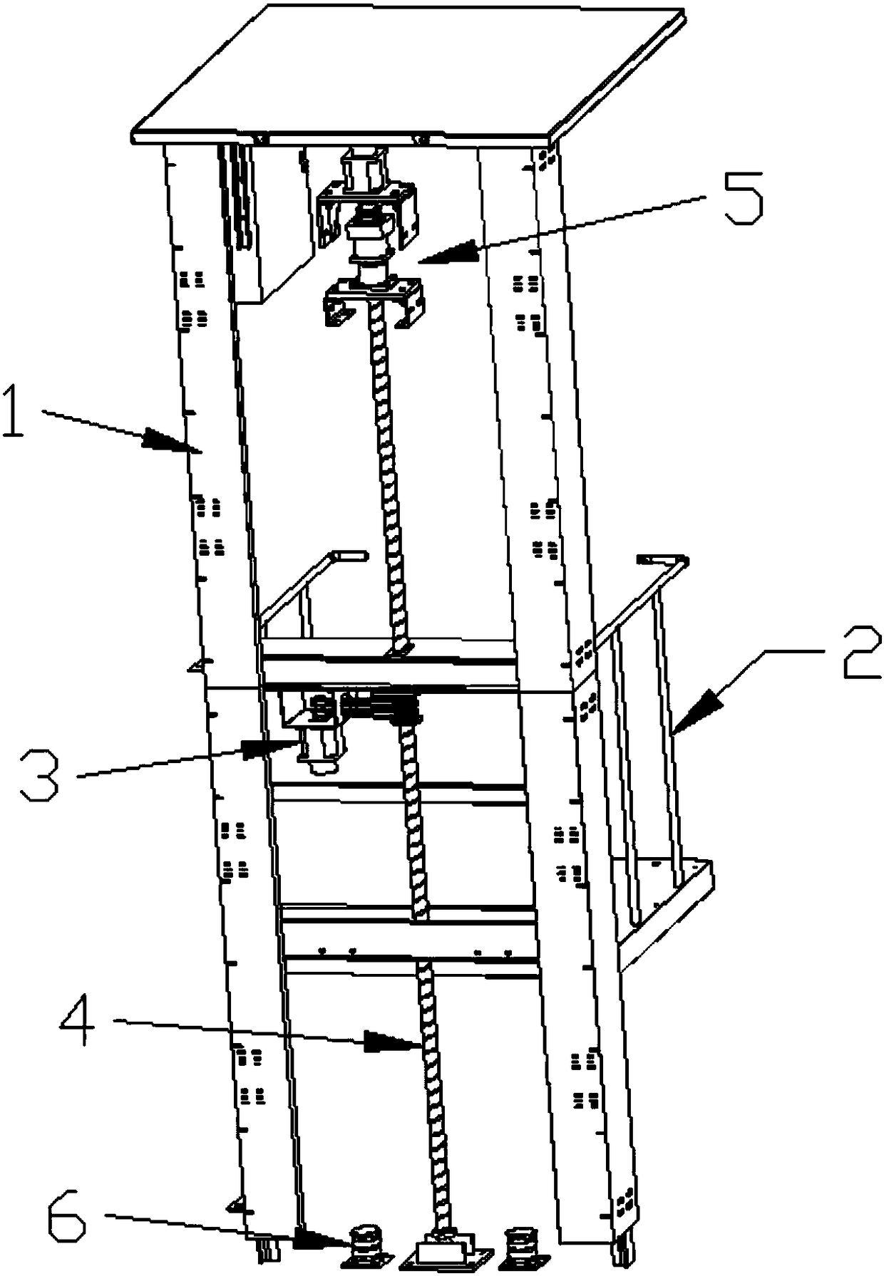
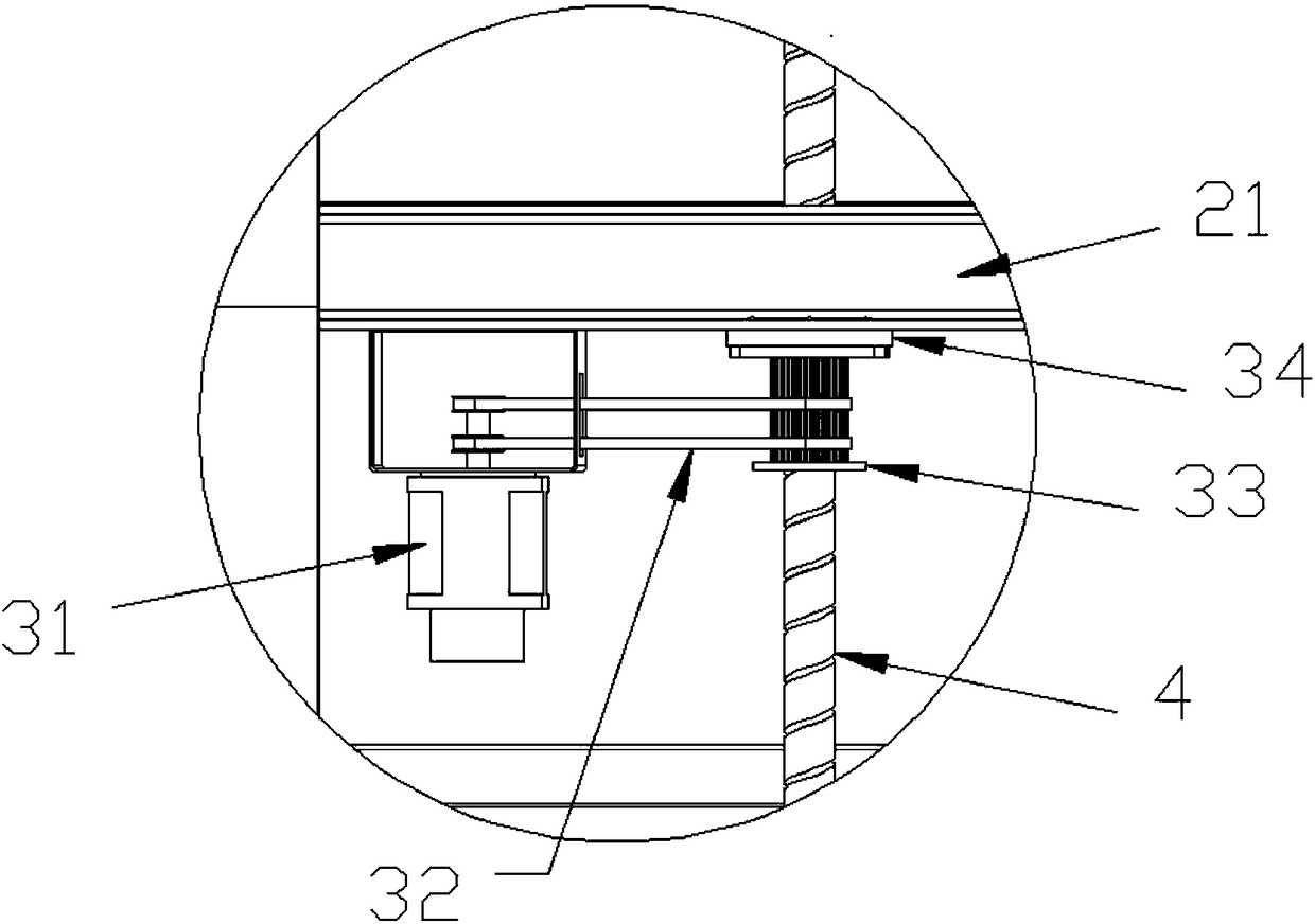
[0035] refer to Figure 1 to Figure 3 , a multi-drive safety lift, comprising a guide rail assembly 1, a car assembly 2 running on the guide rail assembly 1, a first power output module 3 driving the car assembly 2 to run on the guide rail assembly 1, the first power The output module 3 includes an active power output drive and a ball screw 4, wherein:

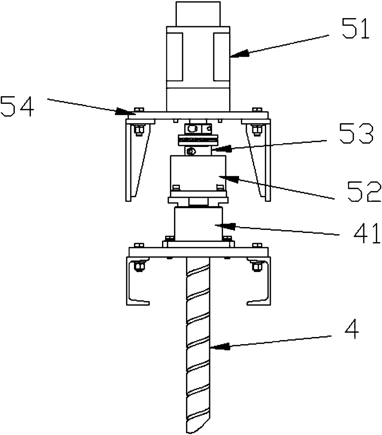
[0036] Also includes a second power output module 5, the second power output module 5 is arranged on the top of the ball screw, the second power output module 5 includes,

[0037] A servo motor 51 is fixed on the motor mounting plate 54 for power output;

[0038] A shaft coupling 53 installed on the output shaft of the servo motor 51 for power transmission;

[0039] A two-way overrunning clutch 52 is flange-connected to the bearing seat 41 on the top of the ball screw 4, wherein one end is connected to the sh...


PUM


Abstract

The invention provides a multi-drive safe lifting elevator. The multi-drive safe lifting elevator comprises a guide rail assembly, a lift car assembly running on the guide rail assembly, and a first power output module driving the lift car assembly to run on the guide rail assembly. The first power output module comprises a main power output drive and a lead screw. A second power output module isfurther included, and the second power output module is arranged at the top end or the bottom end of the lead screw. The second power output module comprises a servo motor fixed to a motor installingplate and used for outputting power, a coupler installed on an output shaft of the servo motor and used for transmitting the power, and a two-way overrun clutch connected with a bearing block flange on the top of the lead screw, wherein one end of the two-way overrun clutch is connected with the coupler, and the other end of the two-way overrun clutch is connected with the lead screw. The safety performance of the elevator is improved, a steel wire rope or steel belt drive mode of a traditional elevator is omitted, the two power output modules independently run, and the functions of mutual acceleration, interference and rescue are achieved.

Description

technical field [0001] The invention relates to the field of elevators, in particular to a multi-drive safety elevator. Background technique [0002] Elevator is a kind of vertical elevator powered by electric motor. The traditional elevator is equipped with a box-like gondola, which is used in multi-storey buildings to take advantage of people or carry goods. Usually a cable suspension structure is used. Such a transmission structure requires a special sling structure on the upper part of the elevator, and a special shaft. The elevator car goes up and down in the shaft, and the elevator car is in use. According to the load of the elevator car, the driving force of the elevator will change greatly. Therefore, the current elevator needs to design the working power of the elevator according to the maximum load when designing the elevator. The shaft above and below the elevator car has a long vertical Once the elevator loses control and falls vertically, it will be very danger...

Claims


Application Information

Patent Timeline
IPC IPC(8): B66B9/02B66B11/04B66B5/02
CPCB66B5/02B66B9/025B66B11/0446
Inventor 陈少洋曹小翠
Owner 陈少洋
Learn More