
Non-contact detection device and detection method for abrasion condition of groove of elevator traction wheel

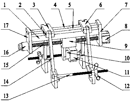
A detection device, elevator traction technology, applied in the direction of transportation and packaging, elevators, etc., can solve the problems of car vibration, uneven tension, low efficiency, etc., and achieve the effects of small human interference, convenient clamping and high testing accuracy

Pending Publication Date: 2018-05-22
GUANGDONG INSPECTION & RES INST OF SPECIAL EQUIP ZHUHAI INSPECTION INST +1
View PDF0 Cites 9 Cited by
  • Summary
  • Abstract
  • Description
  • Claims
  • Application Information

AI Technical Summary

Problems solved by technology

In addition, the uneven tension of the same group of steel wire ropes or the inconsistent shape and depth of the traction sheave's own groove when it leaves the factory will cause uneven wear of the traction sheave during use.
The wear of the traction wheel groove to a certain extent will affect the overall traction performance of the elevator, and it is easy to produce abnormal phenomena such as wire rope slipping and car vibration, which will directly lead to a decrease in ride comfort and even threaten the safety of passengers' lives and property
[0003] At present, the detection of the wear condition of the elevator traction wheel groove is carried out by contact measuring devices such as vernier calipers or plug gauges. The test accuracy of these two methods is greatly affected by the operation method of the tester, and only one wheel groove can be tested at a time. Results are recorded manually, which is inefficient
In addition, the existing contact measurement technology can usually only obtain the data of the wear depth of the wheel groove, but cannot measure the overall profile of the wheel groove, and the comprehensive analysis of the wear condition of the traction wheel groove has certain limitations

Method used


Image

  • Non-contact detection device and detection method for abrasion condition of groove of elevator traction wheel
  • Non-contact detection device and detection method for abrasion condition of groove of elevator traction wheel
  • Non-contact detection device and detection method for abrasion condition of groove of elevator traction wheel

Examples


Embodiment Construction

[0042] In order to enable those skilled in the art to better understand the technical solutions of the present invention, the present invention will be further described in detail below in conjunction with specific examples. The embodiments described below are exemplary only for explaining the present invention and should not be construed as limiting the present invention. If no specific technique or condition is indicated in the examples, it shall be carried out according to the technique or condition described in the literature in this field or according to the product specification.

[0043] The following disclosure provides many different embodiments or examples for implementing different structures of the present invention. To simplify the disclosure of the present invention, components and arrangements of specific examples are described below. Of course, they are only examples and are not intended to limit the invention. Furthermore, the present disclosure may repeat r...


PUM


Abstract

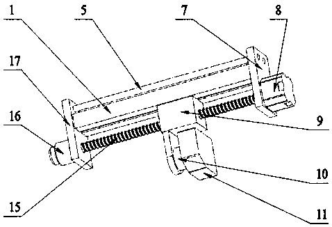
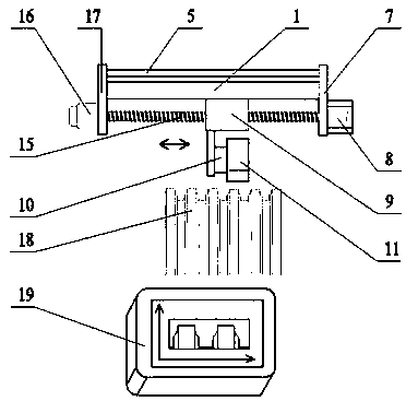
The invention provides a non-contact detection device and a detection method for the abrasion condition of a groove of an elevator traction wheel. The non-contact detection device comprises a drivingunit, a clamping unit, a detection unit and a control display unit, wherein the clamping unit is arranged on the driving unit, the driving unit drives the clamping unit to move, the detection unit ismatched with the clamping unit so as to detect the abrasion condition of the groove of the traction wheel, the control display unit is connected with the detection unit and is used for controlling thedetection unit to move and displaying the abrasion condition of the groove of the traction wheel, and a plurality of characteristic geometric dimensions of the groove are extracted through an algorithm. The device has the advantages of being high in detection precision, high in test time, convenient to operate and the like.

Description

technical field [0001] The invention belongs to the technical field of elevator detection, and in particular relates to an elevator traction sheave detection device, in particular to a non-contact detection device and a detection method for the abrasion condition of an elevator traction sheave wheel groove. Background technique [0002] As the main component of the elevator traction system, the traction sheave plays an important role in ensuring the safe operation of the elevator. During the long-term use of the elevator traction sheave, the sheave grooves are in direct contact with the wire rope, which inevitably causes surface wear. In addition, the uneven tension of the same group of steel wire ropes or the inconsistent shape and depth of the traction sheave's own groove when it leaves the factory will cause uneven wear of the traction sheave during use. The wear of the traction wheel groove to a certain extent will affect the overall traction performance of the elevator...

Claims


Application Information

Patent Timeline
Patent Type & Authority Applications(China)
IPC IPC(8): B66B5/00
CPCB66B5/0031
Inventor 陈建勋陈英红崔大光林晓明孔令昌张俊豪邰胜林
Owner GUANGDONG INSPECTION & RES INST OF SPECIAL EQUIP ZHUHAI INSPECTION INST
Learn More