
Multifunctional plant aerial fog cultivation equipment

An aerosol cultivation and multi-functional technology, applied in the field of plant cultivation equipment, can solve the problems of uneven lighting of vegetables, inconvenient maintenance and the like

Inactive Publication Date: 2018-05-22
冯志高 +3
View PDF12 Cites 0 Cited by
  • Summary
  • Abstract
  • Description
  • Claims
  • Application Information

AI Technical Summary

Problems solved by technology

——The patented solution solves the problem of uneven lighting of vegetables, but the oxygen supply box is installed on the top of the main support, which is inconvenient to maintain

Method used


Image

  • Multifunctional plant aerial fog cultivation equipment
  • Multifunctional plant aerial fog cultivation equipment
  • Multifunctional plant aerial fog cultivation equipment

Examples


Embodiment 1

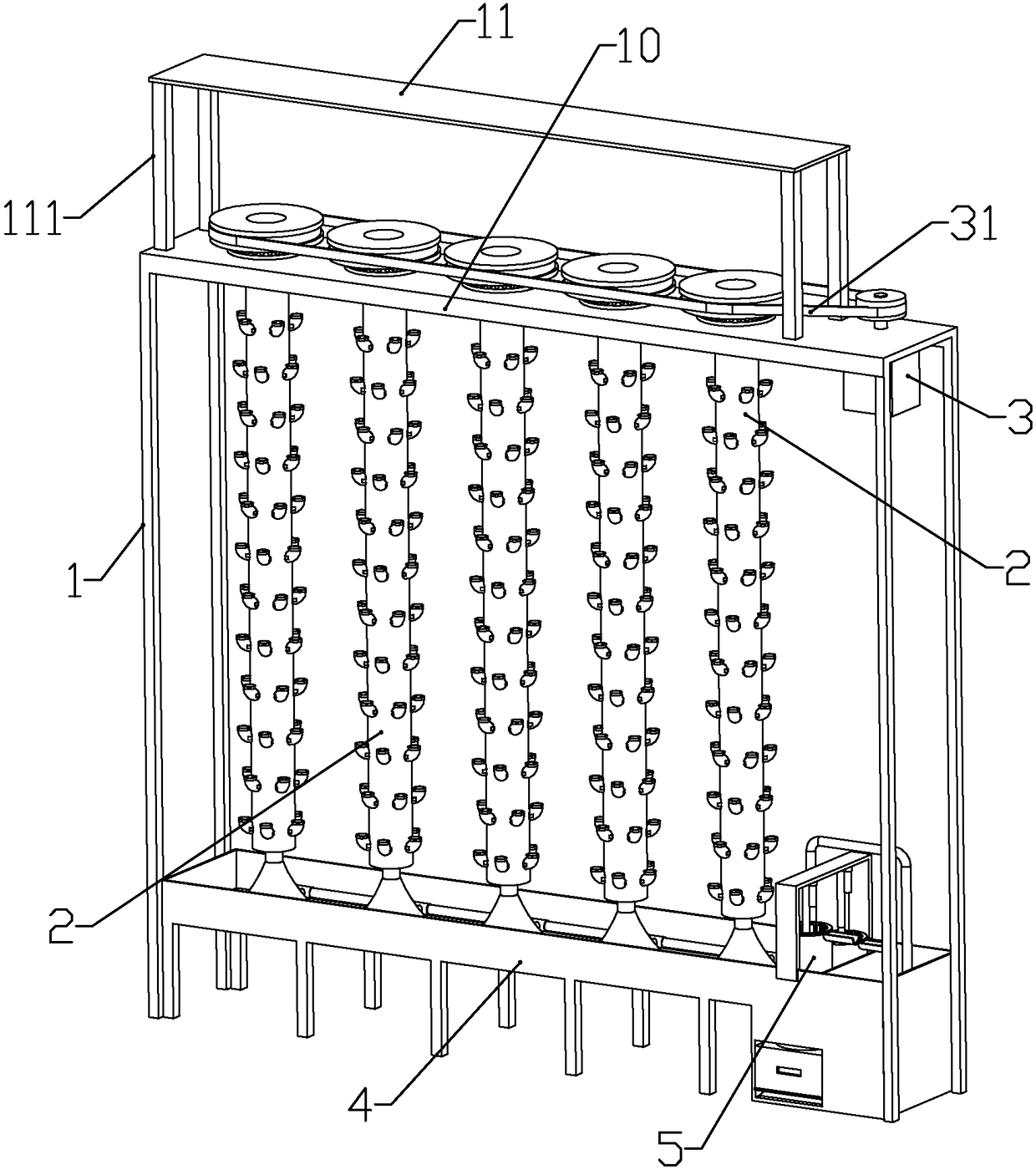
[0095] according to Figure 1 to Figure 15 As shown, the present embodiment is a multifunctional plant aerosol cultivation equipment, including a support 1, a plurality of longitudinally arranged planting components 2 rotatably mounted on the lower end of the support, and a water tank 4 arranged below each planting component.

[0096] A horizontal mounting plate 10 is fixedly connected to the upper end of the bracket, a solar panel mounting frame 111 is fixedly connected to the top of the mounting plate, and a solar battery panel 11 is mounted on the upper end of the solar panel mounting frame.

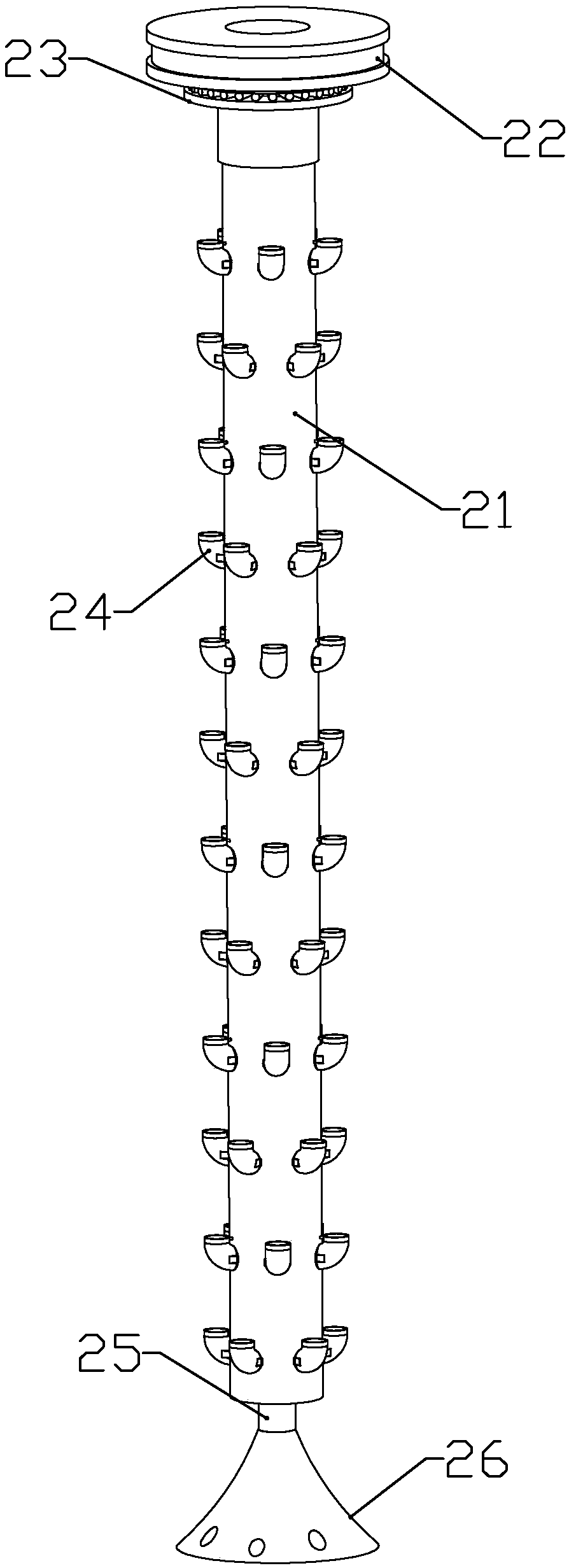
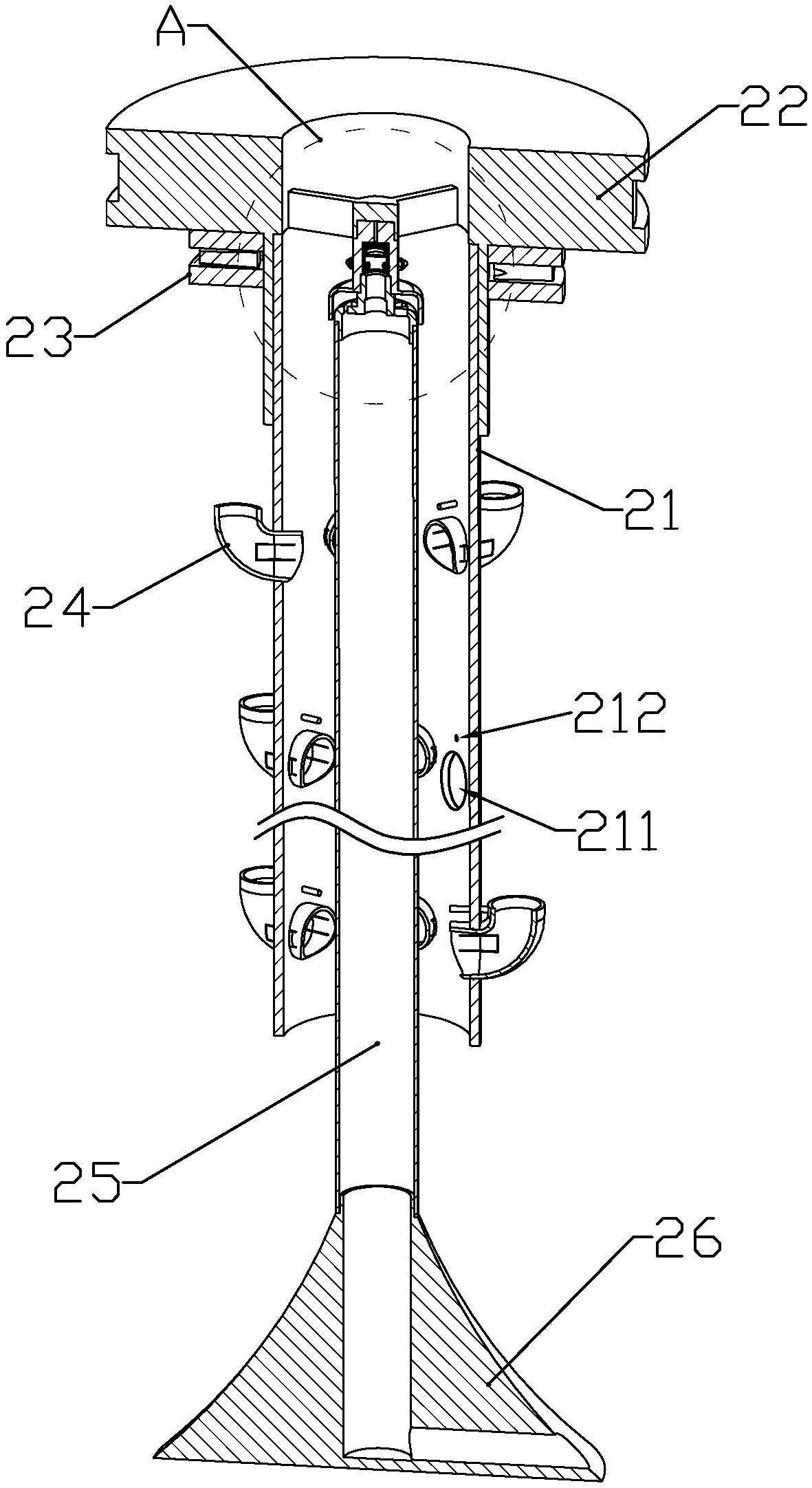
[0097] The planting assembly includes a pulley 22 arranged horizontally above the mounting plate, a bearing 23 connected between the mounting plate and the pulley (the bearing is a radial-axial composite bearing), and a planting plate coaxially connected to the lower end of the pulley. Pipe 21, a plurality of planting elbows 24 installed on the outer wall of the planting pipe and comm...

Embodiment 2

[0117] This embodiment also makes the following improvements on the basis of Embodiment 1: the lower end of the water receiving tank body 41 is formed with two longitudinally arranged cylindrical filter installation ports 44 near the clean water tank body, and the water tank is located on two A waste water tank installation port 43 arranged horizontally is formed below the first filter installation port, and a filter assembly 5 is respectively slidably installed in the two filter installation ports, and a waste water box 52 is installed in the waste water tank installation port.

[0118] Two waste water tanks 521 are formed on the waste water box 52; more than two upper bumps 421 are formed on the inner bottom of the waste water tank installation opening, and a lower slope 4211 is formed on the side of the upper protrusion close to the opening of the waste water tank installation opening; A clamping push plate 54 is slidingly installed at the bottom of the installation opening ...

Embodiment 3

[0132] This embodiment makes the following improvements on the basis of Embodiment 1 or 2: the part of the bracket located below the mounting plate is covered with a cover made of a transparent film or acrylic plate, and the upper part of the cover is connected to an input channel connected to the room. trachea. In this way, the filtered air can be introduced into the room, that is, the present invention can be used as an air purifier.


PUM


Abstract

The invention discloses multifunctional plant aerial fog cultivation equipment. The multifunctional plant aerial fog cultivation equipment is characterized by comprising a support, multiple longitudinally-arranged field planting assemblies rotationally installed at the lower end of the support, and a water channel arranged below the field planting assemblies; the upper end of the support is fixedly connected with a horizontal installing plate, each field planting assembly comprises a belt wheel located above the installing plate and horizontally arranged, a bearing connected between the installing plate and the belt wheel, a field planting pipe coaxially connected to the lower end of the belt wheel, multiple field planting elbows installed on the outer wall of the field planting pipe and communicated with the interior of the field planting pipe, a water inflow pipe coaxially arranged in the field planting pipe, and a fixed base fixedly connected to the lower end of the water inflow pipe and fixedly installed at the inner bottom of the water channel; a drive motor is installed on the installing plate, and the belt wheels on the field planting assemblies are in drive connection withthe drive motors through drive belts; the drive motors and a solar cell panel are electrically connected with a controller. Growth of plants is promoted, and meanwhile air can be purified.

Description

technical field [0001] The invention belongs to the field of plant cultivation equipment, and in particular relates to a multifunctional plant aerosol cultivation equipment. Background technique [0002] The Chinese utility model patent with the publication number CN204994390U discloses a rotary soilless cultivation frame for organic vegetables, including a support, a feeding box, and an aerosol cultivation pot. The support is tree-shaped and includes a main support and several side supports. The side brackets are perpendicular to the main bracket, and are staggeredly arranged on both sides of the main bracket. The feeding box is placed on the top of the main bracket, and the aerosol cultivation pot is placed on the side bracket. The utility model can rotate daylighting, increase Large lighting area, and a floating plate with a cultivation support is installed on the aerosol cultivation pot of the soilless cultivation frame to stabilize the growth of organic vegetables. ——T...

Claims


Application Information

Patent Timeline
Patent Type & Authority Applications(China)
IPC IPC(8): A01G31/06A01G27/00B01D29/52B01D29/03B01D29/64
CPCA01G27/005A01G27/008A01G31/06B01D29/03B01D29/52B01D29/6415Y02P60/21
Inventor 周佳君
Owner 冯志高
Learn More