
Angle bracket drilling jig

A drilling jig and foot code technology, which is applied in the direction of manufacturing tools, clamping, and supports, can solve the problems of misoperation, low yield, low production efficiency, etc., and achieves improved product yield, low manufacturing cost, and structural simple effect

Inactive Publication Date: 2018-05-18
SUZHOU TABINUO ELECTROMECHANICAL
View PDF5 Cites 2 Cited by
  • Summary
  • Abstract
  • Description
  • Claims
  • Application Information

AI Technical Summary

Problems solved by technology

The more holes that need to be drilled on the part, the more obvious the disadvantages of this traditional operation method, which is prone to human error, low yield rate and low production efficiency

Method used


Image

  • Angle bracket drilling jig
  • Angle bracket drilling jig
  • Angle bracket drilling jig

Examples


Embodiment Construction

[0017] The present invention will now be further described in detail in conjunction with the accompanying drawings and embodiments. These drawings are all simplified schematic diagrams, only illustrating the basic structure of the present invention in a schematic manner, so it only shows the composition related to the present invention.

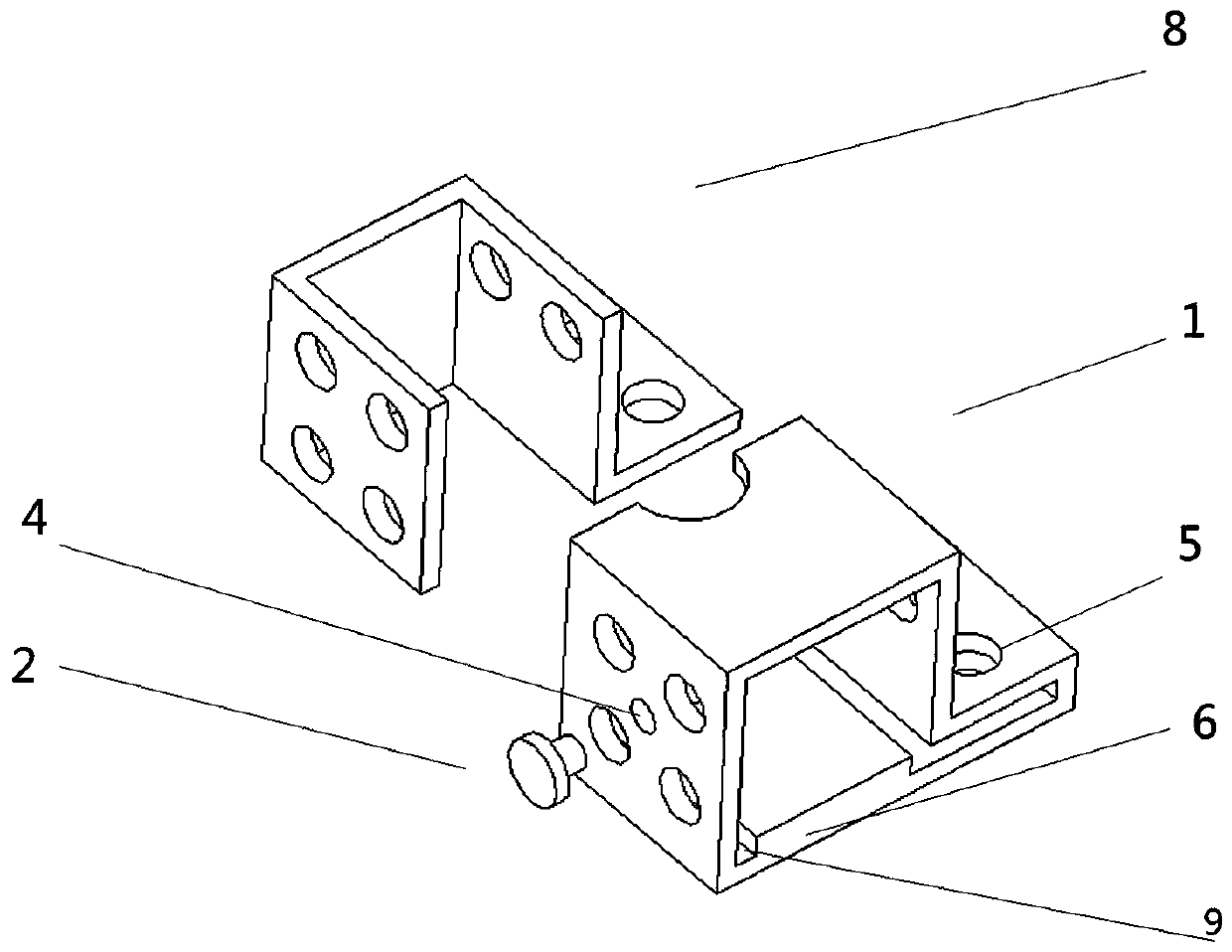
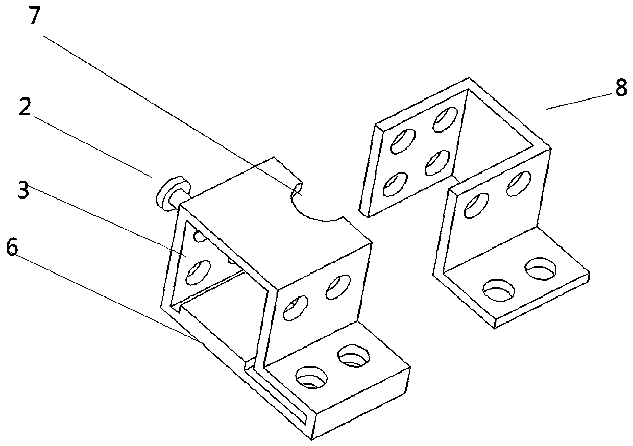
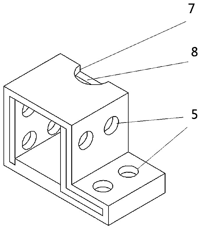
[0018] like Figure 1 to Figure 4 As shown, the foot code drilling jig of the present invention has an integral structure, and is formed with a bottom surface, a side surface, a top surface, a bottom surface, a side surface, and the top surface to encircle a cavity 3 for accommodating the foot code. There are guide holes on the wall to determine the drilling position of the feet, and there are fixing holes on the side walls. The bottom surface is provided with a support platform to prevent the deformation of the feet and a guide groove to save time and effort when pushing the parts into the jig. , the top surface, the bottom surface or both o...


PUM


Abstract

The invention relates to a mechanical jig, in particular to an angle bracket drilling jig. The angle bracket drilling jig is characterized in that a jig main body is of an integrated structure and isprovided with a bottom surface, side faces and a top surface, and a containing cavity is defined by the bottom surface, the side faces and the top surface, wherein the containing cavity is used for containing an angle bracket; guide holes for determining the drilling positions of the angle bracket are formed in the side faces, and the angle bracket is fixed in a fixing hole in the containing cavity of the angle bracket through a screw; and a supporting table for preventing the angle bracket from deforming is arranged on the bottom surface, and the top surface and the bottom surface are provided with part taking-out ports enabling the angle bracket to be conveniently separated from the jig after drilling is finished. The angle bracket drilling jig is simple in structure and is used for machining the angle bracket, so that on one hand, working efficiency is improved, on the other hand, accuracy of drilling is improved, and the yield of products is improved.

Description

technical field [0001] The invention relates to a mechanical jig, in particular to a foot drilling jig. Background technique [0002] In industrial production, the feet are widely used to reliably fix two or more parts, and also have the characteristics of easy disassembly. In order to achieve this effect, it is necessary to drill holes on the feet and the connected parts, and then connect them with bolts, screws, rivets and other fasteners. In the process of making feet, the traditional drilling method is to drill directly on the parts Holes, this method either requires the operator to locate the center of each hole on the foot yard, and then drill each hole, or first locate the center of a hole, drill a hole, and then locate the next Drill the center position of a hole, and then drill the next hole, and then repeat the above process until all the holes are processed. The more holes that need to be drilled on the part, the more obvious the disadvantages of this traditiona...

Claims


Application Information

Patent Timeline
IPC IPC(8): B23Q3/06
CPCB23Q3/062
Inventor 杨保强
Owner SUZHOU TABINUO ELECTROMECHANICAL
Learn More