
Manipulator

A technology of manipulators and motor shafts, applied in the field of manipulators, can solve problems such as expensive, inconvenient grasping, and complex manipulator structures, and achieve the effects of easy operation, space saving, and enhancement of enterprise competitiveness

Inactive Publication Date: 2018-05-15
ANHUI FANCHANG COUNTY WANNAN VALVE CASTING
View PDF10 Cites 9 Cited by
  • Summary
  • Abstract
  • Description
  • Claims
  • Application Information

AI Technical Summary

Problems solved by technology

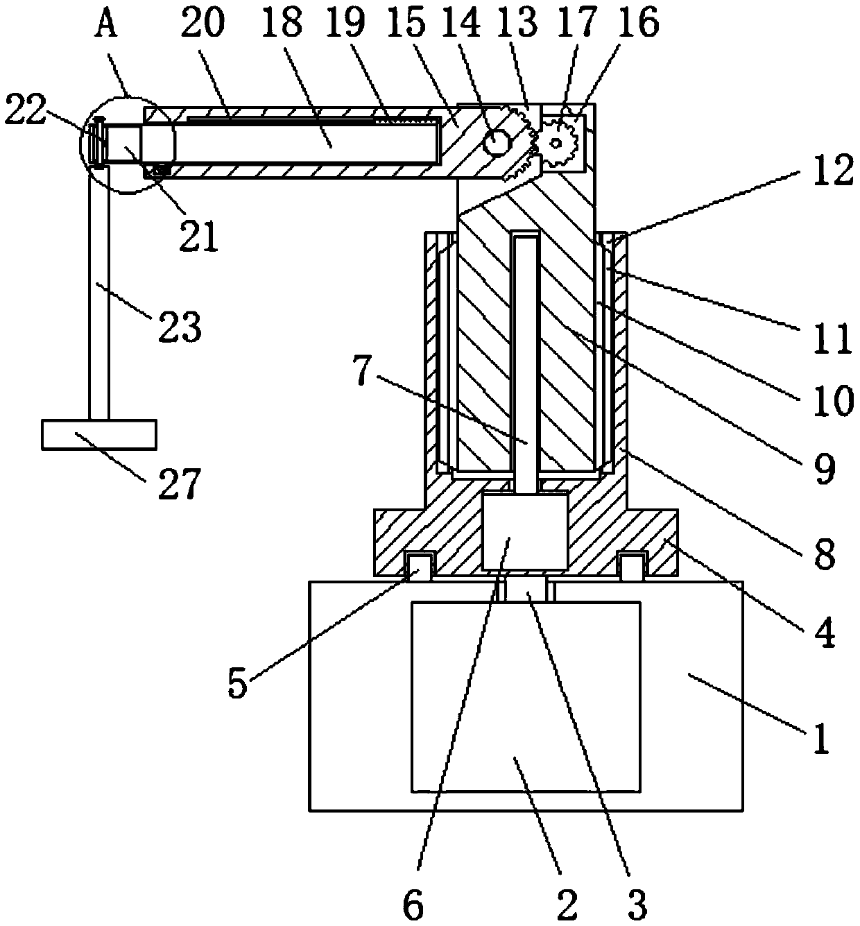
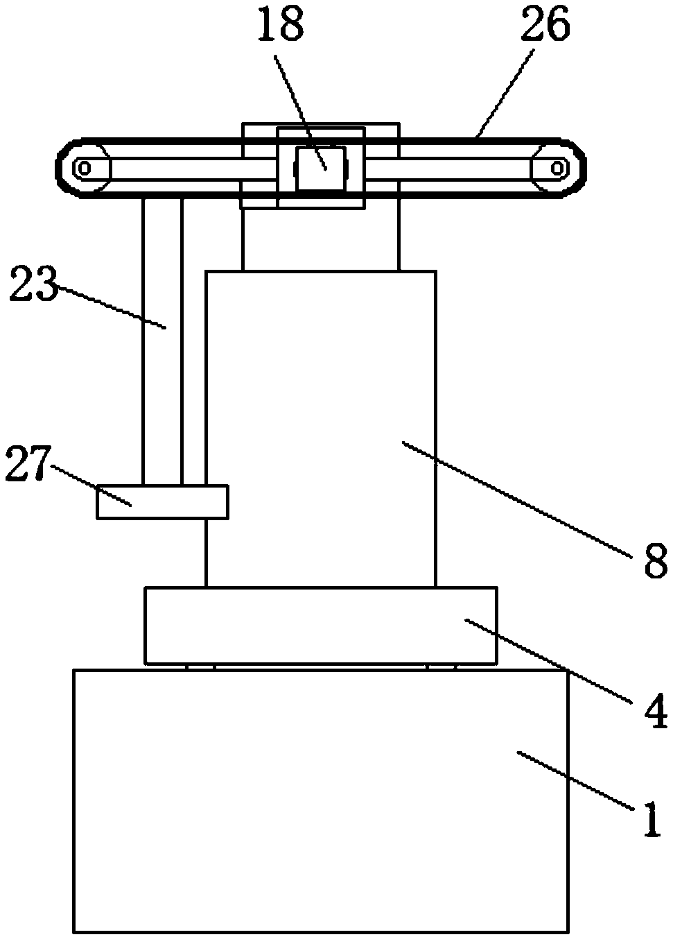
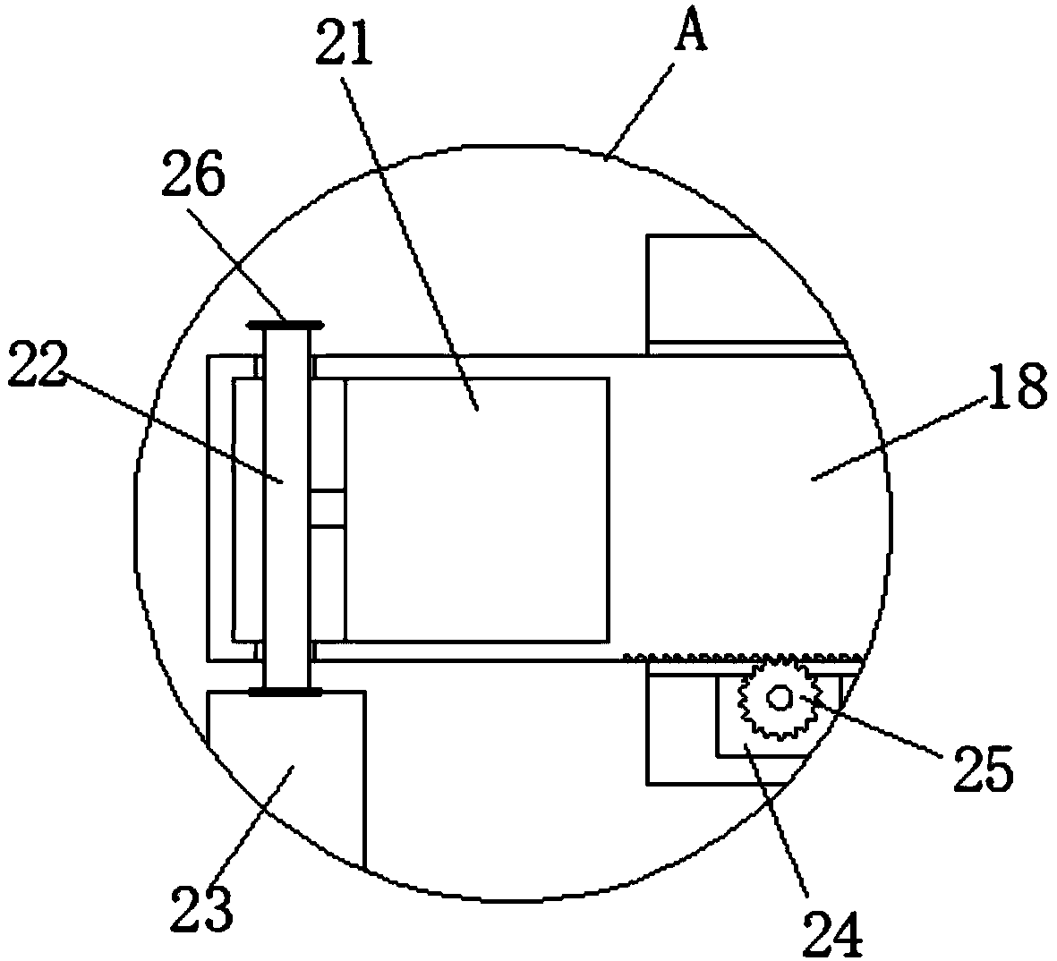
[0004] The purpose of the present invention is to solve the problem that the manipulator in the prior art is complex in structure, expensive and inconvenient to grab workpieces, and proposes a manipulator

Method used


Image

  • Manipulator
  • Manipulator
  • Manipulator

Examples


Embodiment Construction

[0017] The following will clearly and completely describe the technical solutions in the embodiments of the present invention with reference to the accompanying drawings in the embodiments of the present invention. Obviously, the described embodiments are only some, not all, embodiments of the present invention.

[0018] In describing the present invention, it should be understood that the terms "upper", "lower", "front", "rear", "left", "right", "top", "bottom", "inner", " The orientation or positional relationship indicated by "outside", etc. is based on the orientation or positional relationship shown in the drawings, and is only for the convenience of describing the present invention and simplifying the description, rather than indicating or implying that the referred device or element must have a specific orientation, so as to Specific orientation configurations and operations, therefore, are not to be construed as limitations on the invention.

[0019] refer to Figure ...


PUM


Abstract

The invention discloses a manipulator. The manipulator comprises a base, wherein a first mounting cavity is formed in the base; a first rotating motor is mounted in the first mounting cavity; a firstmotor shaft is mounted at a driving end of the first rotating motor, penetrates through the top wall of the inside of the first mounting cavity and extends to the upper side of the base; a mounting seat is arranged on the upper side of the base; the bottom wall of the mounting seat is fixedly connected with a first motor shaft; a plurality of rollers are symmetrically mounted on the bottom wall ofthe mounting seat; a first fixing arm is arranged on the top wall of the mounting seat; and a first mounting hole is formed in the top end of the first fixing arm. The manipulator is simple in structure and easy to implement; the manipulator is adjusted in various directions through multiple different driving modes; the most suitable driving mode is used for the different positions; the occupiedspace and manufacturing cost are greatly saved; demands of daily production can be met completely; meanwhile, the manipulator is convenient to operate; the factor of safety is high; and the enterprisecompetitiveness is improved.

Description

technical field [0001] The invention relates to the technical field of mechanical devices, in particular to a manipulator. Background technique [0002] At present, in the welding, assembly, die-casting and other mechanical processing production processes, it is generally necessary to take and discharge the workpiece, but in many mechanical processing production processes, manual operations are used to carry out the material taking and discharging operations. The operation is inconvenient, the production efficiency is low, and it is easy to damage and dirty the workpiece, and the automatic production can ensure the high precision, high quality and high efficiency requirements of the product, so the automatic manipulator is widely developed and applied to the molding machine and machine tool , assembly lines, die-casting machines and other equipment or devices to perform operations such as moving objects and sucking workpieces, but most of the existing technologies use clamps...

Claims


Application Information

Patent Timeline
Patent Type & Authority Applications(China)
IPC IPC(8): B25J9/12B25J15/06
CPCB25J9/104B25J9/12B25J15/0608
Inventor 沈升好
Owner ANHUI FANCHANG COUNTY WANNAN VALVE CASTING
Learn More