
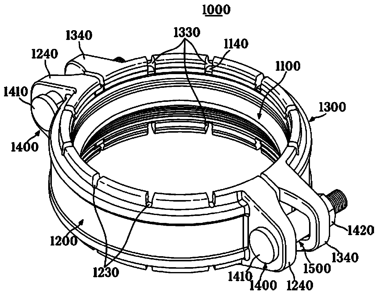
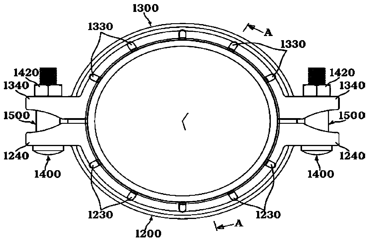
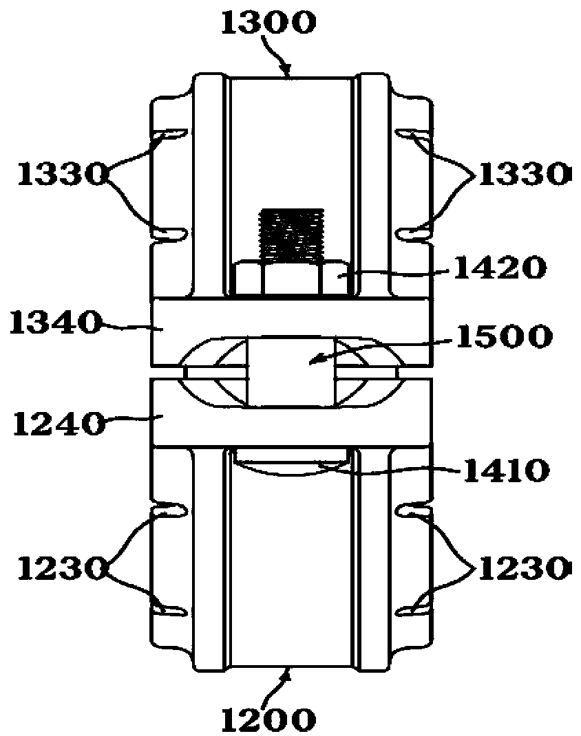
Earthquake-proof grooveless coupling

A technology of pipe joints and grooved pipes, which is applied in the field of pipe joints, can solve the problems of difficult assembly operations, prolonged operation time, and obstruction of fluid flow, etc., and achieve the effect of good fluid flow and simple operation procedures

Inactive Publication Date: 2018-05-11
南相建
View PDF1 Cites 1 Cited by
  • Summary
  • Abstract
  • Description
  • Claims
  • Application Information

AI Technical Summary

Problems solved by technology

[0006] However, the process of opening the annular outer groove on the pipe is very complicated, and requires an operating space to install machinery for processing, and when the annular outer groove is formed, it also protrudes to the inner diameter side by a certain amount to hinder the flow of fluid , resulting in poor fluid flow and vibration
[0007] This kind of pipe joint is prone to water leakage when the pipe is newly built. When assembling the pipe joint segment on the pipe, it is necessary to unscrew the bolts and nuts, clamp the sealing parts into the pipe, and then place the pipe on the upper and lower parts of the pipe. When the bolts and nuts are tightened while the joint segments are in close contact, it is difficult to twist the part protruding inward of the pipe joint segment and caught in the ring-shaped outer groove of the pipe, which makes the assembly work extremely difficult. , resulting in much longer working time

Method used


Image

  • Earthquake-proof grooveless coupling
  • Earthquake-proof grooveless coupling
  • Earthquake-proof grooveless coupling

Examples


Embodiment Construction

[0065] The vibration-resistant grooveless pipe joint of the embodiment of the present invention will be described in detail below with reference to the accompanying drawings.

[0066] When adding reference signs to multiple components of the above-mentioned drawings, even if the same component is marked on different drawings, the same symbol should be used as far as possible. For known functions that are considered to obscure the gist of the present invention and structures are not specified. Directional terms such as "upper", "lower", "front", "rear", "front end", "front", "rear end" are used for orientation in many of the drawings. The constituent elements of the embodiments of the present invention can be positioned in various orientations, so the terminology of directions is only an example, not a limitation.

[0067] The vibration-resistant grooveless pipe joint 1000 of the first embodiment of the present invention is as Figure 1 to Figure 9 As shown, it includes: an e...


PUM


Abstract

The present invention relates to an earthquake-proof grooveless coupling for enabling pipes to be connected only by pushing a grooveless pipe into both sides thereof in a state in which upper and lower coupling segments are assembled and fastening a bolt and a nut. The earthquake-proof grooveless coupling (1000) of the present invention comprises: a packing (1100) made from an elastic material andinto which pipes (1, 2) for transferring fluid are fitted from the left and right sides thereof; the upper and lower coupling segments (1200, 1300) for encompassing the packing at the upper and lowerparts thereof so as to accommodate the same, and restricting the axial movements of the pipes (1, 2) at both end portions thereof as the segments become closer to each other; and a fastening means (1400) comprising the bolt (1410) and the nut (1420) for fastening the upper and lower coupling segments to each other, wherein the upper and lower coupling segments have holding parts (1220, 1320) formed in a saw-toothed shape and respectively provided at both end portions (1210, 1310) in the direction of the central axis of the inner peripheral surface thereof, the holding parts are formed to be smaller than the radii of the pipes (1, 2) and formed to have greater hardness than the pipes (1, 2), and the upper and lower coupling segments have cut grooves (1230, 1330) formed to have a predetermined width in the axial direction at equal angles in the radial direction of both end portions (1210, 1310) in the direction of the central axis of the inner peripheral surface thereof, and formed in aslot shape so as to be positioned between the outer diameter of the holding part and the inner diameter of a packing accommodating groove.

Description

technical field [0001] The invention relates to a pipe joint, in particular, an anti-seismic grooveless pipe joint which is connected at the end of the pipe but does not need to be grooved when connecting a fluid delivery pipe or pipeline. Background technique [0002] Usually most buildings should have automatic sprinkler system for fire extinguishing according to the regulations. Moreover, the demand for fire extinguishing systems in residential buildings is gradually increasing. [0003] For these fire-fighting piping systems using metal pipes for fluid conveyance, the law was amended to stipulate that these pipes cannot be welded, and the pipes need to be connected mechanically, as described in Korean Patent Registration No. The CPVC fire-fighting self-supporting automatic sprinkler system and its assembly method of the device and supporting device" discloses that the pipe and the pipe form an annular outer groove isolated from the end to the axial direction, and the an...

Claims


Application Information

Patent Timeline
Patent Type & Authority Applications(China)
IPC IPC(8): F16L21/06F16L21/08F16L17/06F16B2/06
CPCF16B2/12F16L17/04F16L21/005F16B2/06F16L17/06F16L21/065F16L21/08F16L21/06
Inventor 南相建
Owner 南相建
Learn More