
Tapping device using vacuum and tapping control method

A control method, a vacuum technology, applied in the manufacture of converters, etc., can solve the problem that the siphon effect is not easy to realize, and achieve the effects of shortening the power off time, improving productivity, and preventing the mixing of slag

Active Publication Date: 2018-05-11
POSCO ENG & CONSTR
View PDF4 Cites 0 Cited by
  • Summary
  • Abstract
  • Description
  • Claims
  • Application Information

AI Technical Summary

Problems solved by technology

However, the utilization of the siphon effect has the problem of not being easy to implement due to various constraints

Method used


Image

  • Tapping device using vacuum and tapping control method
  • Tapping device using vacuum and tapping control method
  • Tapping device using vacuum and tapping control method

Examples


Embodiment Construction

[0028] Hereinafter, embodiments of the present invention will be described with reference to the drawings. However, the embodiments of the present invention can be modified into various forms, and the scope of the present invention is not limited to the embodiments described below. In order to illustrate more clearly, the shapes and sizes of elements in the drawings may be shown enlarged, and elements denoted by the same reference numerals in the drawings refer to the same elements.

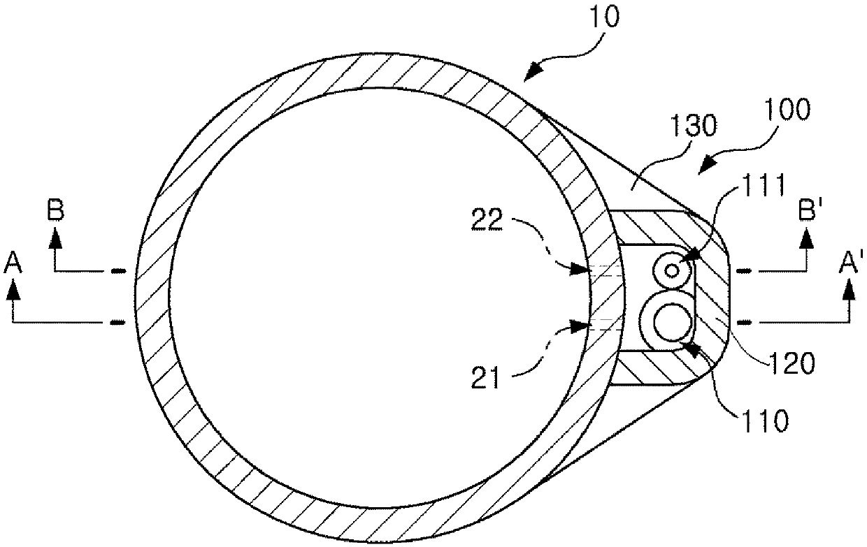
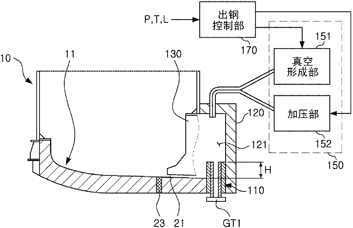
[0029] figure 1 It is a top view of a tapping device applied to a furnace body according to an embodiment of the present invention, figure 2 will be figure 1 Side view taken along line A-A`. on the one hand, Figure 10 to Figure 13 A furnace body to which a tapping device according to an embodiment of the present invention can be applied is shown.

[0030] Such as figure 1 as well as figure 2 As shown, the tapping device 100 according to an aspect of the present invention may be installe...


PUM


Abstract

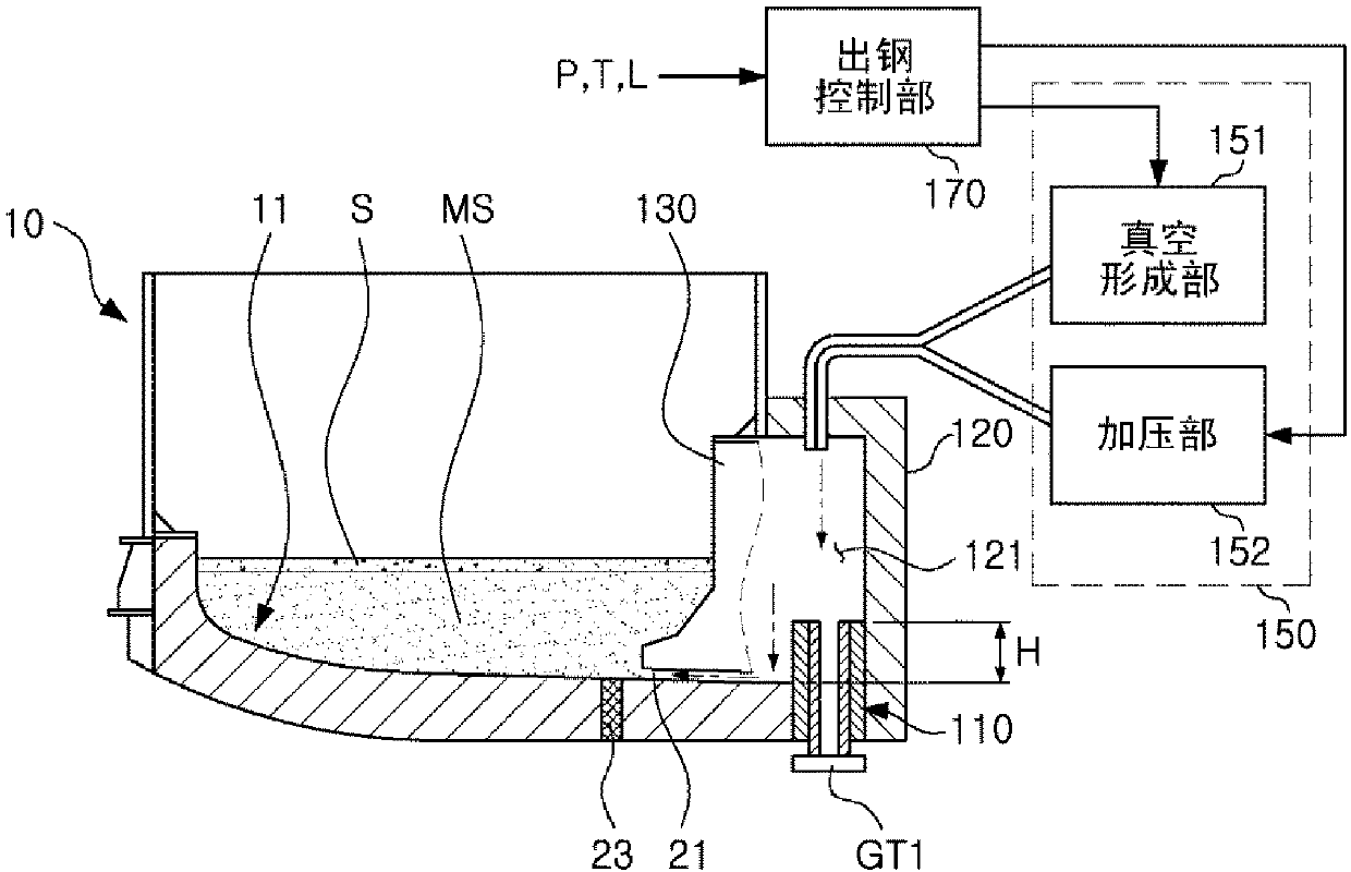
A tapping device using vacuum according to an embodiment of the present invention may comprise a sealing-type chamber, which seals a molten steel outlet formed on the lower portion of a side surface of a furnace body, and which is configured to be able to adjust the internal pressure thereof; and a first tapping spout formed to penetrate the lower portion of the sealing-type chamber such that molten steel, which has been introduced through the molten steel outlet, is discharged to the outside, the first tapping spout having an upper portion formed to protrude from the lower portion of the furnace body to a predetermined height.

Description

technical field [0001] The application relates to an inclined or non-inclined molten steel treatment device. Background technique [0002] Generally, methods for discharging molten steel using an electric furnace device roughly include an eccentric bottom tapping (EBT: Eccentric Bottom Tapping) method, a spout method, a siphon method, and the like. [0003] In order to discharge the molten steel in the furnace, the EBT method needs to tilt the furnace body too much, so there is a problem of slag flowing out during tapping. The tapping spout method discharges all the molten steel stored in the furnace body at one time during tapping, so it is difficult to remove the molten steel. Containing slag problem. [0004] On the one hand, the siphon method is an effective device for discharging molten steel without flowing out the slag. However, the utilization of the siphon effect has the problem of not being easy to realize due to various constraints. That is, in order to utilize...

Claims


Application Information

Patent Timeline
Patent Type & Authority Applications(China)
IPC IPC(8): C21C5/46C21C5/28C21C7/10
CPCC21C5/28C21C5/46C21C7/10
Inventor 郑炳圭高昌柱金景镐闵德基成勇周陈乙德
Owner POSCO ENG & CONSTR
Learn More