Electric power optical cable fiber fusion sleeve and manufacturing method thereof

A technology of optical cable and electric power, which is applied in the direction of optics, light guides, optical components, etc., can solve the problems of fiber coating failure, fiber transmission interruption, etc., and achieve the effect of reducing operation and maintenance costs, reducing defects, and promoting safe operation rate

Pending Publication Date: 2018-05-11
STATE GRID HUBEI ELECTRIC POWER CO XIAOGAN POWER SUPPLY CO
View PDF0 Cites 0 Cited by
  • Summary
  • Abstract
  • Description
  • Claims
  • Application Information

AI Technical Summary

Problems solved by technology

[0005] In order to overcome the defects of the prior art, the technical problem to be solved by the present invention is to provide a power optical cable fusion fiber sleeve, which completely solves the problem of the power system substation, transmission line, and power plant in the strong electromagnetic field environment after the optical fiber is spliced. The failure of the fiber coating caused by the heating and burning of the fused fiber sheath tube and the deformation caused by the fiber optic transmission in the middle of the problem has improved the safe operation rate of UHV, EHV, high-voltage transmission lines and substation power fiber optic backbone networks, and eliminated The hidden dangers of the backbone line equipment of optical cables in the smart grid have promoted the safe operation rate of the power grid, reduced the shortage and maintenance work of the backbone lines of power optical cables, and greatly reduced the operation and maintenance costs of power grid enterprises

Method used


Image

  • Electric power optical cable fiber fusion sleeve and manufacturing method thereof
  • Electric power optical cable fiber fusion sleeve and manufacturing method thereof
  • Electric power optical cable fiber fusion sleeve and manufacturing method thereof

Examples


Embodiment Construction

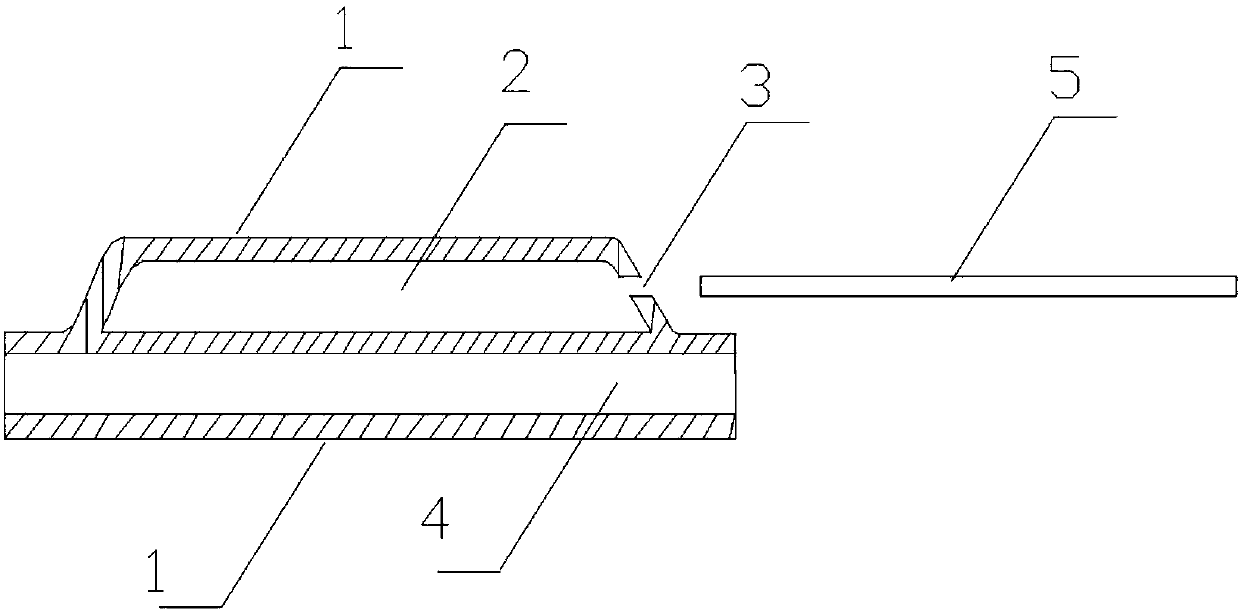
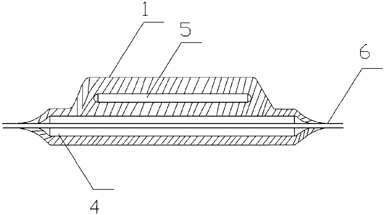
[0017] At present, the fused fiber sheath tube of domestic and foreign power optical cables adopts the fused fiber sheath tube of the telecommunication cable. Since the reinforcing shank of the fused fiber sheath tube is a steel wire with a diameter of 1.5mm and a length of 45mm, the fusion of this ferromagnetic material The fiber sheath tube will generate heat due to electromagnetic induction in a strong electromagnetic field environment, especially for power optical fiber cables used in AC ultra-high voltage substations, AC ultra-high voltage substations, AC high-voltage substations, power plant generators, transformers, and AC transmission lines. After splicing, during operation, the fiber optic channel is often interrupted due to heat and combustion of the fused fiber sheath tube, which directly threatens the safe production of the power grid. Due to the vigorous development of smart grids in recent years, power optical fiber communication has been rapidly built with smart ...


PUM


Abstract

The invention provides an electric power optical cable fiber fusion sleeve, which solves the problem of interruption of optical fiber transmission due to optical fiber coating failure caused by heating combustion and deformation of the fiber fusion sleeve occurring in the operation process after optical fiber splicing in the strong electromagnetic field environment of power system substations, power transmission lines and power plants, and improves safety operation rate of an electric fiber backbone network. The electric power optical cable fiber fusion sleeve comprises a nonmetal non-magneticreinforced rib and an integrated protective tube coat. The protective tube coat comprises an optical fiber protection tube cavity and a rib placing cavity. The optical fiber protection tube cavity isa cavity, the two ends of which are opened. A welding fiber core is inserted into the optical fiber protection tube cavity and is then, welded in the optical fiber protection tube cavity. The rib placing cavity is arranged above the optical fiber protection tube cavity, and is a cavity, one end of which is closed and the other end of which has a rib placing port. The nonmetal non-magnetic reinforced rib is inserted into the rib placing cavity from the rib placing port, and then, is pressed and packaged in the rib placing port. The electric power optical cable fiber fusion sleeve is used for optical cable fiber splicing in the strong electromagnetic field environment of ultra-high-voltage, super-high-voltage and high-voltage substations, power transmission lines, power plants and industrial chemical, ship and medical industry equipment. The invention also provides a manufacturing method thereof.

Description

technical field [0001] The present invention relates to the technical field of power systems, in particular to a power optical cable fusion fiber sleeve and a manufacturing method thereof, which are mainly used in ultra-high voltage, ultra-high voltage, and high-voltage substations, power transmission lines, power plants, and equipment in industrial chemicals, ships, and medical industries Fiber optic cable splicing in strong electromagnetic field environment. Background technique [0002] At present, OPGW, OPPC, OPLC, ADSS, AD-LASH, and GWWOP optical cables are used in UHV, EHV, and HV substations and transmission lines in domestic and foreign power systems. Because these optical cables are operated in substations and high electromagnetic field environments in transmission lines, the fiber cores in the splicing box are often fused, and the fiber cores and sheaths at the fiber sleeves are burned, causing fiber channel transmission to be interrupted, resulting in grid automat...

Claims


Application Information

Patent Timeline
Patent Type & Authority Applications(China)
IPC IPC(8): G02B6/44
CPCG02B6/255G02B6/443G02B6/4432G02B6/4479
Inventor 张悦饶渝泽赵阳涂弘娟夏雨杨帆张晓华
Owner STATE GRID HUBEI ELECTRIC POWER CO XIAOGAN POWER SUPPLY CO
Why Eureka
Try Eureka