
Magnetic-levitation wind-driven laser scanning radar

A technology of laser scanning radar and magnetic levitation, which is applied to the re-radiation of electromagnetic waves, the use of re-radiation, and measuring devices. It can solve the problems of high noise, short service life, and high price, and achieve long life and low noise.

Active Publication Date: 2018-05-11
SUZHOU UNIV
View PDF6 Cites 4 Cited by
  • Summary
  • Abstract
  • Description
  • Claims
  • Application Information

AI Technical Summary

Problems solved by technology

However, the current laser ranging sensors are generally expensive, and there are disadvantages such as high noise and short service life, which are unacceptable to robot enthusiasts.

Method used


Image

  • Magnetic-levitation wind-driven laser scanning radar
  • Magnetic-levitation wind-driven laser scanning radar
  • Magnetic-levitation wind-driven laser scanning radar

Examples


Embodiment 1

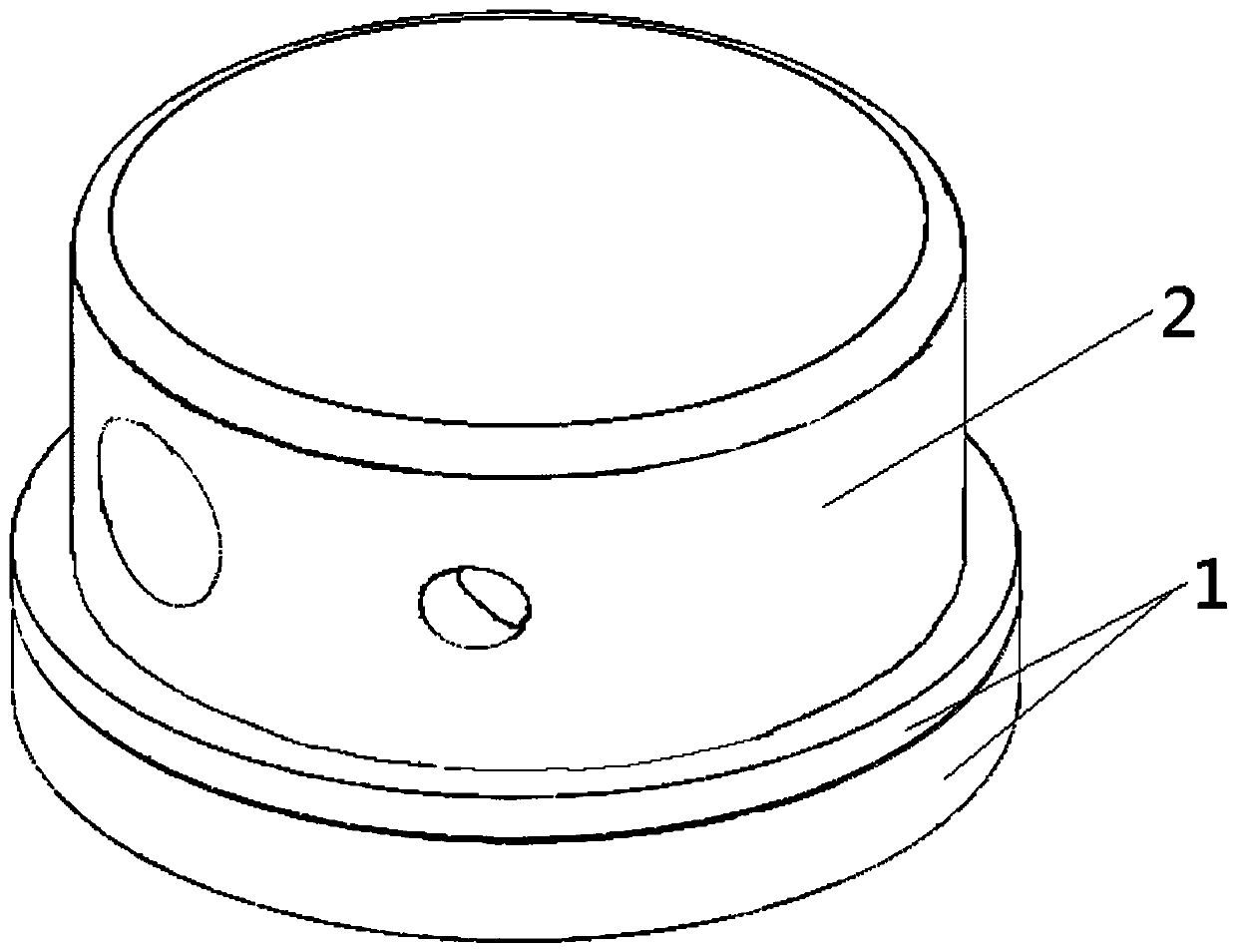
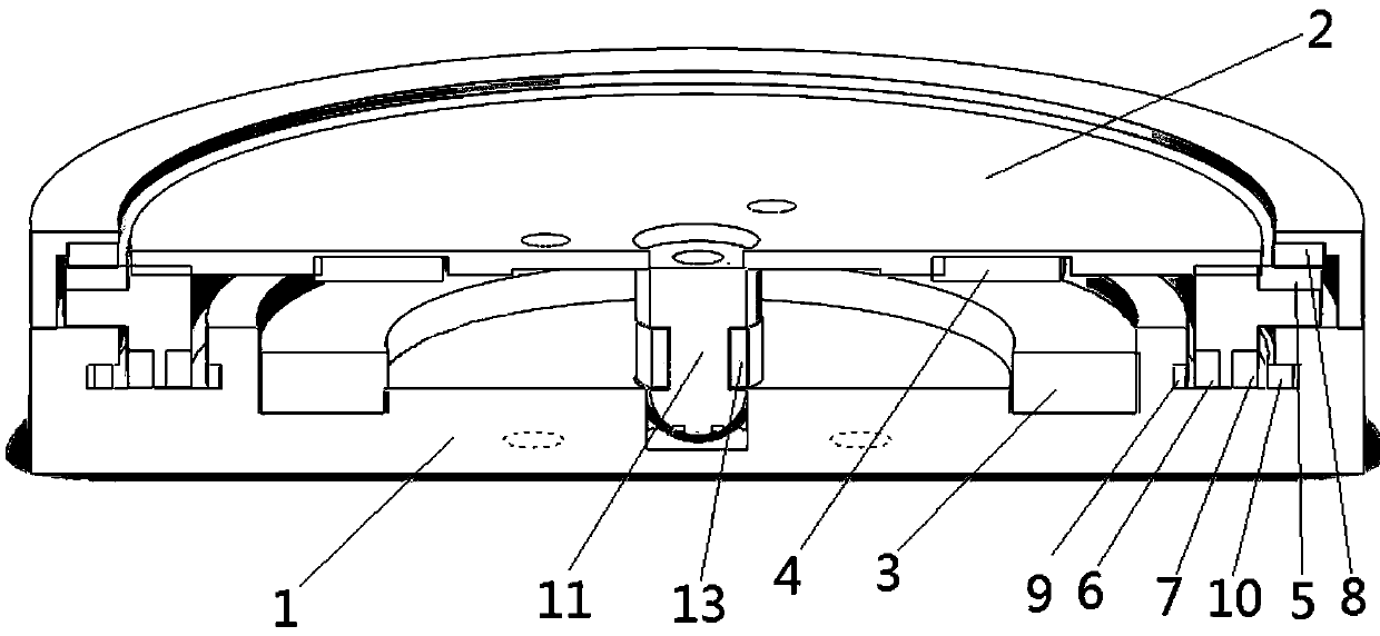
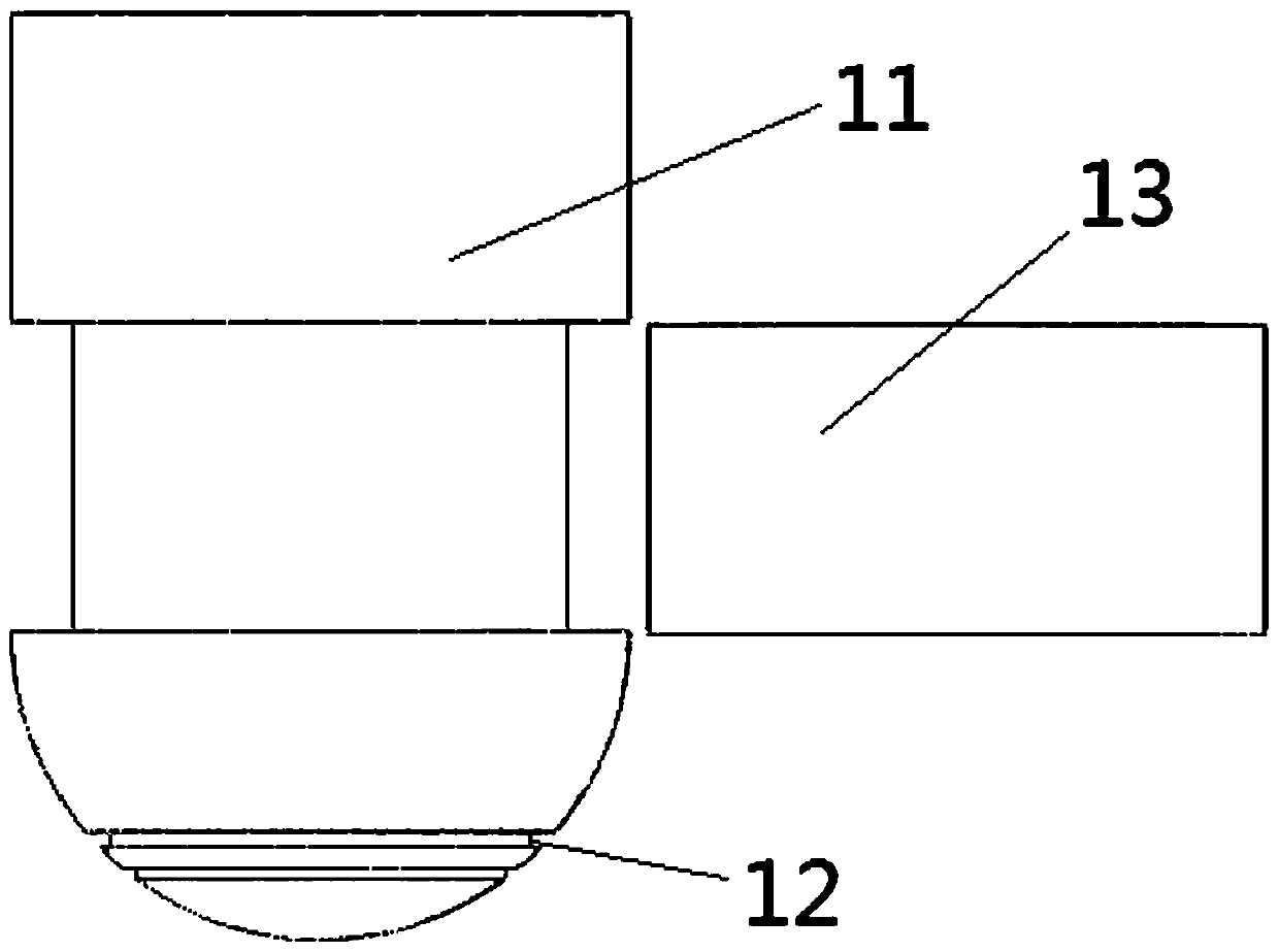
[0026] Embodiment one: see Figure 1~Figure 4 As shown, a maglev wind-driven laser scanning radar includes an image processing system, a rotating platform 2, a fixed platform 1, a magnetic ring group and a wind-driven cooling device,

[0027] The image processing system is set in the rotating platform,

[0028] The rotating platform 2 is arranged above the fixed platform 1,

[0029] see figure 2 As shown, where the rotating platform is not completely drawn, the magnetic ring group includes a suspension system and a guiding system, and the suspension system includes a large magnetic ring 3 and a small magnetic ring 4 that are arranged up and down oppositely, wherein the large magnetic ring 3 is embedded Set on the fixed platform 1, the small magnetic ring 4 is embedded on the rotating platform 2, the large magnetic ring 3 is fixed and nested on the lower fixed platform with a large mass, and the small magnetic ring 4 is fixed and nested on the lower fixed platform with a rel...


PUM


Abstract

The invention relates to a magnetic-levitation wind-driven laser scanning radar comprising an image processing system, a rotating platform, a fixed platform, a magnetic ring group and a wind-driven heat dissipation device. The image processing system is arranged in the rotating platform arranged above the fixed platform. The magnetic-levitation wind-driven laser scanning radar not only has functions of distance measurement and three-dimensional cloud map drawing but also has advantages of reduced usage noise and long service life.

Description

technical field [0001] The invention relates to a maglev wind-driven laser scanning radar, which belongs to the technical field of laser radar scanning. Background technique [0002] Machine vision is the use of machines instead of human eyes for measurement and judgment. With the gradual improvement of optical technology, image analysis and other technologies, through the automatic recognition function of machine vision, many highly repeatable inspections on the assembly line can be completed quickly, which greatly improves the inspection efficiency and accuracy. The invention of various small robots has also put forward higher requirements for low-cost small ranging and navigation sensors. The laser ranging sensor can perform fast and accurate positioning and is currently the most commonly used sensor in SLAM (instant positioning and map construction) technology. SLAM was first proposed by Smith, Self and Cheeseman in 1988. Due to its important theoretical and applicatio...

Claims


Application Information

Patent Timeline
Patent Type & Authority Applications(China)
IPC IPC(8): G01S17/06G01S7/481
CPCG01S7/4817G01S17/06
Inventor 魏巍李群龙章鹏程程李丹夏禹轩赵升杰
Owner SUZHOU UNIV
Learn More