
Plug-flow type reactor and controlling method of biogas produced by utilizing cow dung

A reactor and plug-flow technology, which is applied in the field of plug-flow reactor and its regulation of biogas production by using cow dung, can solve the problems of high construction cost, low organic matter utilization rate and methane recovery rate, and low gas production. Achieve the effect of low operating cost, high gas production rate and high biogas output

Pending Publication Date: 2018-05-11
HARBIN INST OF TECH
View PDF3 Cites 1 Cited by
  • Summary
  • Abstract
  • Description
  • Claims
  • Application Information

AI Technical Summary

Problems solved by technology

[0005] The invention aims to solve the technical problems of high operation construction cost of biogas production from livestock and poultry manure and low efficiency of energy recovery, organic matter utilization rate and methane recovery rate, especially to solve the problem of lower gas production obtained by using substrates with high fiber content To solve the technical problems, provide a new type of reactor and its biogas production regulation method and microbial community structure

Method used


Image

  • Plug-flow type reactor and controlling method of biogas produced by utilizing cow dung
  • Plug-flow type reactor and controlling method of biogas produced by utilizing cow dung
  • Plug-flow type reactor and controlling method of biogas produced by utilizing cow dung

Examples


Embodiment Construction

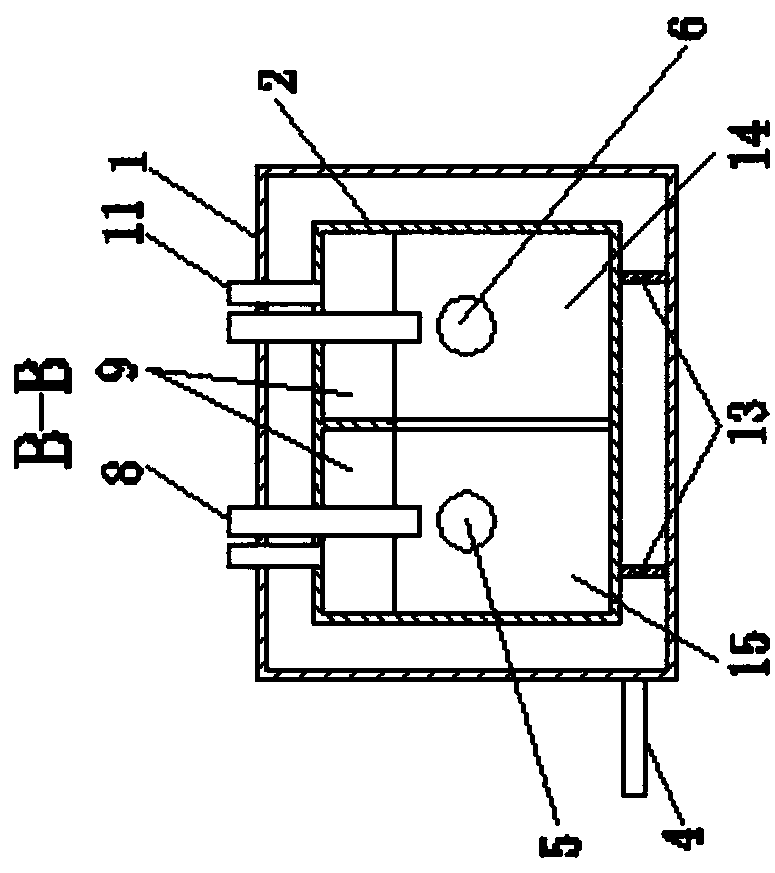
[0035] Specific implementation mode one: combine Figure 1-3 To illustrate, a plug-flow reactor in this embodiment is processed from plexiglass, including an outer box 1 and a main reactor 2, and the outer box 1 of the plug-flow reactor (PFR) is set In the main reactor 2, a cavity is formed between the outer box 1 and the main reactor 2, and hot circulating water is introduced into the cavity, and a support plate 13 is provided between the inner surface of the bottom of the outer box 1 and the main reactor 2;

[0036] Main reactor 2 length=1.5m, height=0.15m, width=0.2m;

[0037] In the main reactor 2, the first partition 10 is arranged perpendicular to the bottom plate of the main reactor 2 along the longitudinal direction to divide the main reactor 2 into a first reaction chamber 14 and a second reaction chamber 15; the first reaction chamber 14 and the second reaction chamber The upper part of the chamber 15 is divided into five air chambers by the second partitions 9 arra...


PUM


Abstract

The invention discloses a plug-flow type reactor and a controlling method of biogas produced by utilizing cow dung, belongs to the technical field of environmental protection and biomass energy, and aims to solve the technical problems of low energy recycling efficiency, a low utilization ratio of organic matters and a low methane recycling ratio in an existing fecal residue and waste water anaerobic fermentation technology, in particular to treatment on substrates with high fiber substance contents. The interior of a main body reactor of the plug-flow type reactor disclosed by the invention is divided into two reaction chambers by a partition plate in a long-side direction; the reaction chambers are divided into ten air chambers by partition plates in a short-side direction; an air outletpipe, a sampling pipe, a feeding hole and a discharging hole are also arranged on and formed in the main body reactor; a heat insulation device is arranged on the outer part of the main body reactor.The method disclosed by the invention comprises the following steps: 1, controlling of parameters; 2, starting; 3, stable operation. According to the plug-flow type reactor and the controlling methoddisclosed by the invention, the biogas produced by utilizing anaerobic digestion of fecal residue and waste water with a high solid ratio, fiber substances and sludge is realized, and the plug-flow type reactor has the advantages of no blocking, no maintenance, simple structure, low construction cost, high efficiency, stable operation and easiness for controlling.

Description

technical field [0001] The invention belongs to the technical field of environmental protection and biomass energy; in particular, it relates to a plug-flow reactor and a control method for producing biogas by using cow dung. Background technique [0002] With the rapid development of animal husbandry in our country, the pollution of the ecological environment by livestock manure is becoming more and more serious. If livestock manure cannot be properly disposed of, it will cause serious pollution to the atmosphere, water, and soil, and endanger human health. On the other hand, my country's energy structure dominated by fossil energy has been severely challenged, and there is an urgent need to develop new energy. According to the data released by the China Petroleum Economics and Technology Research Institute, in 2011 China's dependence on foreign natural gas was 26%, and it is predicted that by 2020 the consumption will reach 185 billion m 3 , foreign dependence will be as...

Claims


Application Information

Patent Timeline
IPC IPC(8): C02F11/04C10L3/08C02F103/20
CPCC02F11/04C02F2103/20C10L3/08C10L2200/0461C10L2250/02C10L2290/26Y02E50/30
Inventor 董丽丽任南琪曹广丽郭宪章赵磊
Owner HARBIN INST OF TECH
Learn More