
Roof plate overhead hoist for architectural interior decoration

A technology for interior decoration and lifting devices, which is applied in the processing of building materials, construction, lifting devices, etc., and can solve problems such as increased labor intensity, low work efficiency, and increased number of workers

Active Publication Date: 2018-05-11
THE ELEVENTH METALLURGICAL CONSTR GRP
View PDF2 Cites 10 Cited by
  • Summary
  • Abstract
  • Description
  • Claims
  • Application Information

AI Technical Summary

Problems solved by technology

[0002] Generally, interior decoration needs to be done in many aspects. The walls, floors and ceilings need to be painted. When dealing with the ceiling, a double ladder or some other climbing devices are generally used to facilitate the workers to get close to the indoor roof. The installation of the ceiling in the position, the general ceiling materials are piece by piece, and these ladder climbing devices can only stand people, can not place more installation board materials, these boards need to be delivered manually from the ground by other workers Delivery in such a way is easy to delay time, work efficiency is not high, and it also increases the number of workers required and increases labor intensity

Method used


Image

  • Roof plate overhead hoist for architectural interior decoration
  • Roof plate overhead hoist for architectural interior decoration
  • Roof plate overhead hoist for architectural interior decoration

Examples


Embodiment Construction

[0016] The technical solution of the present patent will be described in further detail below in conjunction with specific embodiments.

[0017] Embodiments of the present patent are described in detail below, examples of which are illustrated in the accompanying drawings, wherein the same or similar reference numerals refer to the same or similar elements or elements having the same or similar functions throughout. The embodiments described below with reference to the accompanying drawings are exemplary and are only used to explain the present patent, but should not be construed as a limitation on the present patent.

[0018] In the description of this patent, it should be understood that the terms "center", "upper", "lower", "front", "rear", "left", "right", "vertical", "horizontal", The orientation or positional relationship indicated by "top", "bottom", "inner", "outer", etc. is based on the orientation or positional relationship shown in the drawings, and is only for the ...


PUM


Abstract

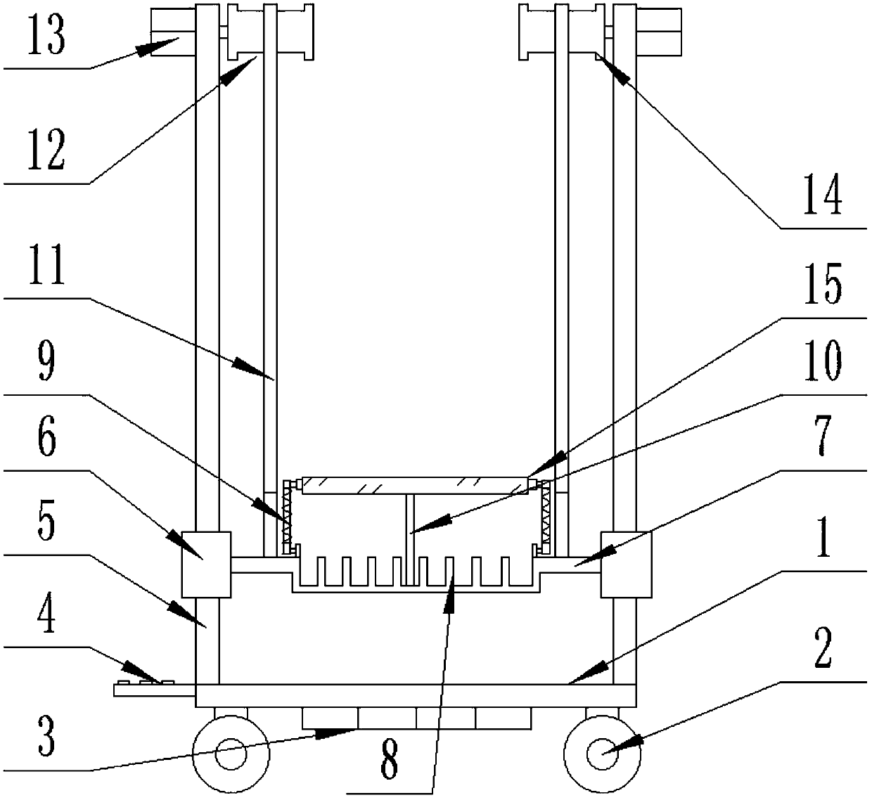
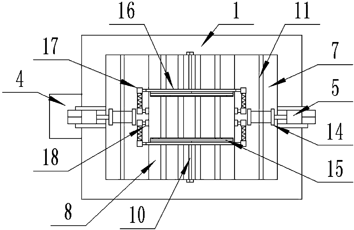
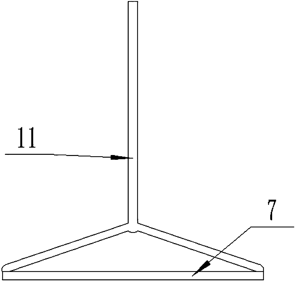
The invention provides a roof plate overhead hoist for architectural interior decoration. The roof plate overhead hoist for architectural interior decoration belongs to the field of architectural interior decoration, and comprises a support plate. The support plate is located at a horizontal position; four top corners of a lower end surface of the support plate are each provided with a universal wheel; midpoint positions of the left side and the right side of an upper end surface of the support plate are each provided with a support pillar in a vertical fixed connection way; a motor is fixedlyconnected to an outer side wall of an upper end head of each support pillar; and a main shaft of each motor horizontally penetrates through the corresponding support pillar from a left-right direction. According to the roof plate overhead hoist for architectural interior decoration provided by the invention, through the universal wheels, the whole device can conveniently move; a hoisting plate isused for placing ceiling materials to be installed in batch, then the main shafts of the motors are started to rotate forwards, and rotary columns rotate to wind hoisting ropes, so that the hoistingplate is hoisted, the ceiling materials get close to a roof, and workers can conveniently take and use the materials in high places for installing; annular grooves are used for preventing the hoistingropes from separating from the rotary column; and clamping plates ensure that the hoisting plate moves in a vertical direction, so that the hoisting plate is prevented from shaking in a horizontal plane to cause the falling of the materials during a hoisting process.

Description

technical field [0001] The invention relates to a building decoration equipment, in particular to a roof plate hoisting device for building interior decoration. Background technique [0002] Generally, interior decoration needs to be done in many aspects. The walls, floors and ceilings need to be painted. When dealing with the ceiling, a double ladder or some other climbing devices are generally used to facilitate the workers to get close to the indoor roof. The installation of the ceiling in the position, the general ceiling materials are piece by piece, and these ladder climbing devices can only stand people, can not place more installation board materials, these boards need to be delivered manually from the ground by other workers Delivery in such a way is easy to delay time, work efficiency is not high, and it also increases the number of workers required and increases labor intensity. Contents of the invention [0003] Aiming at the deficiencies of the above-mentione...

Claims


Application Information

Patent Timeline
IPC IPC(8): B66F7/02B66F7/28E04G21/16
CPCB66F7/02B66F7/28E04G21/162
Inventor 张强
Owner THE ELEVENTH METALLURGICAL CONSTR GRP
Learn More