Automated material conveying device for hardware stamping parts

A technology for stamping parts and feeding materials, applied in the field of metal stamping parts processing and application, can solve the problems of large output, small size of five stamping parts, and inability to fully automate processing.

Inactive Publication Date: 2018-05-11
柳州市鑫裕塑胶有限责任公司
View PDF6 Cites 0 Cited by
  • Summary
  • Abstract
  • Description
  • Claims
  • Application Information

AI Technical Summary

Problems solved by technology

[0004] The purpose of the present invention is to solve the problem that although metal stamping parts can be transported simply, the volume of five stamping parts is usually small, and it is impossible to fully automate the process, and it is impossible to guarantee the safety of the metal stamping parts during transportation. Stability, and the design of the device is mostly complicated and troublesome, the principle is inconvenient to operate, and the problem of small energy consumption and large output cannot be achieved. An automatic feeding device for metal stamping parts is provided

Method used


Image

  • Automated material conveying device for hardware stamping parts
  • Automated material conveying device for hardware stamping parts
  • Automated material conveying device for hardware stamping parts

Examples


Embodiment 1

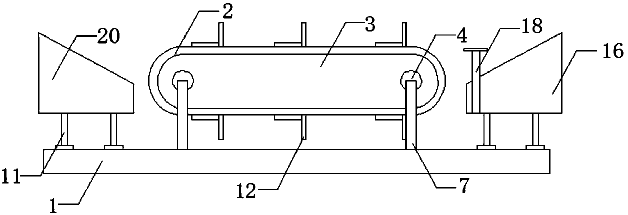
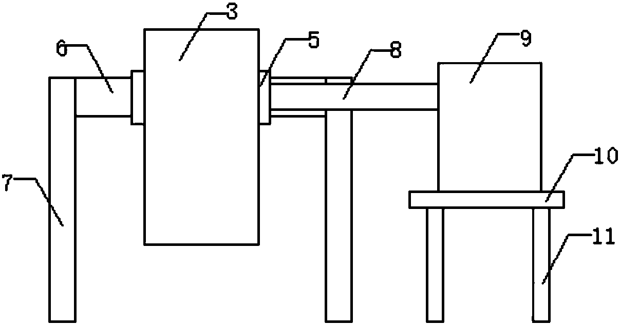
[0026] see Figure 1-6 As shown, an automatic feeding device for metal stamping parts includes a bottom plate 1, a wheel shaft 3, a cross bar 6, a rotating shaft 8, a support plate 10, a vertical plate 12, a screw hole 14, a raw material tank 16, a baffle plate 18 and Outlet chute 20, the base plate 1 is provided with a vertical bar 7, and the top of the vertical bar 7 is horizontally connected to a cross bar 6, and the other end of the cross bar 6 is connected to the adapter block 5, and the adapter block 5 is located in the connection hole 4, the connection hole 4 is located on the wheel shaft 3, by setting the motor 9 and the rotating shaft 3 connected to the pulley 2, the motor 9 rotates, thereby driving the pulley 2 to rotate together, so that on the one hand, it not only provides the rotation of the pulley 2 On the other hand, it is possible to control the speed of the motor 9, thereby adjusting the feeding speed for metal stamping parts, and the outer circumference of t...

Embodiment 2

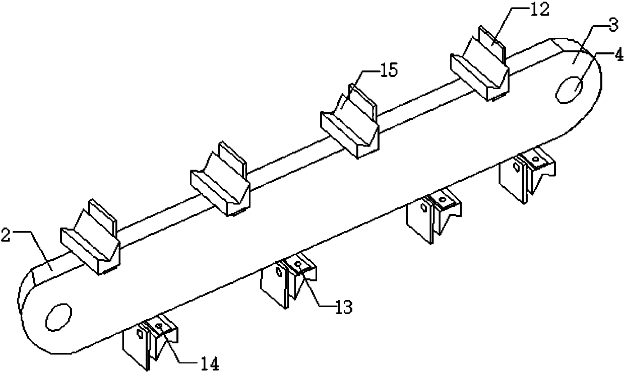
[0028] read on Figure 1-6 As shown, compared with the above-mentioned embodiment, a rotating shaft 8 runs through the inside of the horizontal bar on one side of the wheel shaft 3, and the other end of the rotating shaft 8 is connected to a motor 9, and the motor 9 is movably connected to the wheel shaft 3 through the rotating shaft 8, through The motor 9 is provided, thus giving the pulley 2 a source of power when rotating. The bottom end of motor 9 is provided with support plate 10, and the bottom end of support plate 10 is provided with support leg 11, and the bottom end of raw material tank 16 is also provided with support leg 11, and the bottom end of support leg 11 is positioned on base plate 1, by The legs 11 are provided, thus making it more stable on the base plate 1 . The pulley 2 is vertically provided with several vertical plates 12, and the bottom end of the vertical plate 12 is horizontally provided with several horizontal plates 13, and the vertical plate 12 a...


PUM


Abstract

The invention discloses an automated material conveying device for hardware stamping parts. The automated material conveying device comprises a base plate, a belt pulley, a pulley shaft, connecting holes, through connection blocks, a transverse rod, vertical rods, a rotating shaft, a motor, a support plate, support legs, vertical plates, transverse plates, threaded holes, storage plates, a raw material tank, an article inlet, a baffle, an article outlet and a discharging tank. The automated material conveying device has the beneficial effects that by means of the motor and the rotating shaft connected with the belt pulley, rotation is achieved through the motor, on one hand, a power source is provided for rotation of the belt pulley, and on the other hand, the conveying speed of the hardware stamping parts can be adjusted by controlling the rotating speed of the motor; the baffle is arranged in the raw material tank and can slide up and down in the raw material tank, and therefore, rawmaterials inside the raw material tank can be controlled to be conveyed into and out of the raw material tank; and the problem that when the conveying device does not arrive, the raw materials fall from the article outlet due to the inclined design of the raw material tank, so that disorder is caused and the device cannot be used normally can be avoided.

Description

technical field [0001] The invention relates to an automatic material conveying device, in particular to an automatic material conveying device for metal stamping parts, belonging to the application field of metal stamping parts processing. Background technique [0002] The automatic feeding device for metal stamping parts is a device that can transport metal stamping parts during the processing of metal stamping parts. Because metal stamping parts are widely used in various fields of our life , including some electronic devices, auto parts, decorative materials and so on. The stamping parts we usually refer to are cold stamping parts. For example, if you want to turn a piece of iron plate into a fast food plate, you must first design a set of molds. The working surface of the mold is the shape of the plate. Press the iron plate, and it will become the plate you want. This is cold stamping, which is to stamp the hardware material directly with a mold. [0003] However, the...

Claims


Application Information

Patent Timeline
Patent Type & Authority Applications(China)
IPC IPC(8): B21D43/06
CPCB21D43/06
Inventor 蒙衍强陈卫民韦中明
Owner 柳州市鑫裕塑胶有限责任公司
Why Eureka
Try Eureka