
Method and device for enhancing gas flow rate measurement precision

A technology for measuring accuracy and gas flow rate, which is applied in the field of tunable diode laser absorption spectroscopy, can solve the problems of reduced measurement accuracy and accuracy, inability to meet low-speed measurement and wide-range flow rate measurement, and achieve the effect of improving resolution and accuracy

Active Publication Date: 2018-05-08
TIANJIN POLYTECHNIC UNIV
View PDF6 Cites 8 Cited by
  • Summary
  • Abstract
  • Description
  • Claims
  • Application Information

AI Technical Summary

Problems solved by technology

If the flow velocity of the measured object is lower than 59.40m / s, the measurement precision and accuracy will be reduced, which cannot meet the needs of low-speed measurement and wide-range flow velocity measurement

Method used


Image

  • Method and device for enhancing gas flow rate measurement precision
  • Method and device for enhancing gas flow rate measurement precision
  • Method and device for enhancing gas flow rate measurement precision

Examples


Embodiment 1

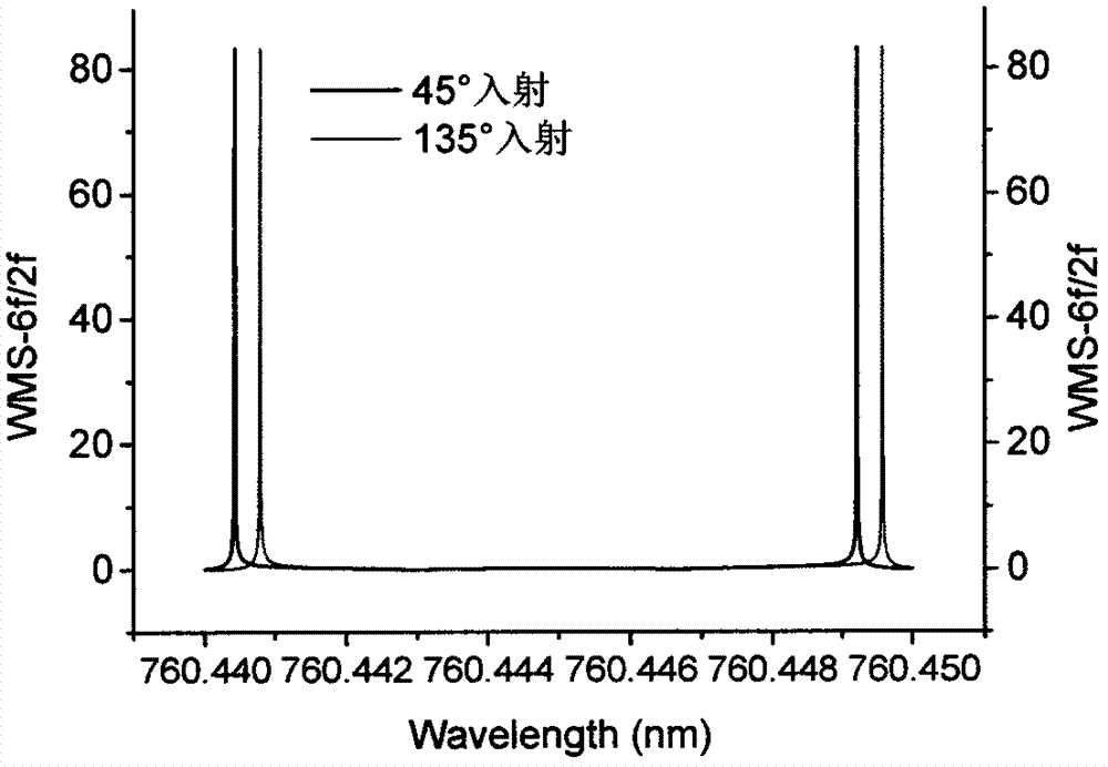
[0035] Embodiment 1: (760nm laser, V gas =100m / s, 4f / 2f)

[0036] The following takes the analysis of the absorption line of oxygen molecules at 760.445nm as an example to illustrate the measurement method for calculating the gas flow rate using this scheme. In this embodiment, we choose the absorption line with a center wavelength of 760.445nm, with θ 1 =45°, θ 2 =135° cross oblique incidence into the air flow field with a flow velocity of 100m / s, set n=4, m=2, that is, two digital lock-in amplifiers are demodulated simultaneously to obtain WMS-4f / 2f signals.

[0037] lambda 0 , nm

lambda 1 , nm

lambda 2 , nm

θ 1

θ 2

760.445

760.44518

760.44482

45°

135°

[0038] T=296K, P=1 atm.

[0039] Air flow rate:

[0040] Using the above formula, the airflow velocity is obtained as V gas =100.44m / s, the relative error is 0.44%. Compared with the measurement with only WMS-2f (relative error about 4.0%), the error is red...

Embodiment 2

[0041] Embodiment 2: (760nm laser, V gas =100m / s)

[0042] The following takes the analysis of the absorption line of oxygen molecules at 760.445nm as an example to illustrate the measurement method for calculating the gas flow rate using this scheme. In this embodiment, we choose the absorption line with a center wavelength of 760.445nm, with θ 1 =45°, θ 2 =135° cross-oblique incidence into the oxygen flow field with a flow velocity of 100m / s, set n=6, m=2, that is, two digital lock-in amplifiers are demodulated simultaneously to obtain WMS-4f / 2f signals.

[0043] lambda 0 , nm

lambda 1 , nm

lambda 2 , nm

θ 1

θ 2

760.445

760.44518

760.44482

45°

135°

[0044] T=296K, P=1 atm.

[0045] Airflow velocity: V gas =λ 0 Δυ / (Cosθ 1 -Cosθ 2 )

[0046] Using the above formula, the airflow velocity is obtained as V gas =101.24m / s, the relative error is 1.24%.

[0047] Thus, the flow velocity of the gas in the experiment i...


PUM


Abstract

The invention belongs to the technical field of high speed gas concentration and flow rate measurement, and discloses a method and a device for enhancing gas flow rate measurement precision. Accordingto the method, two even harmonic signals (nf and mf, n,m=2,4,6... and n>m) are simultaneously demodulated by using a phase-locked amplifier through the wavelength modulation spectrum (WMS) technology, nf (WMS-nf / mf) is normalized by mf and narrow and sharp peak signals of high signal-to-noise ratio are obtained, and the gas flow rate is calculated through Doppler frequency shift of narrow peak sothat the measurement resolution and precision can be enhanced. The device is composed of a tunable laser, a photoelectric detector and the phase-locked amplifier. The working steps of the device arethat two beams of laser and gas flow are obliquely incident to the gas flow field with the directions crossed at a certain angle, the emergent laser is received by two detectors and converted into electric signals, the electric signals are demodulated by the phase-locked amplifier and the WMS-nf / mf signals are obtained, and the flow rate of the gas is calculated through Doppler frequency shift ofthe two signals.

Description

technical field [0001] The invention belongs to the technical field of flow velocity and concentration measurement of high-speed gas, and relates to a method and device of tunable diode laser absorption spectroscopy technology. By implementing the scheme on the spectrum line to be measured of the target gas, the concentration and flow velocity of the gas can be measured while improving the Measurement resolution and accuracy of flow velocity. Background technique [0002] For high-speed flow fields, such as the tail nozzle of aerospace engines, the measurement of gas flow velocity is very important. The traditional speed measurement methods such as Pitot tube, hot wire anemometer, etc., belong to contact measurement, which not only easily cause interference to the combustion process, but also the harsh environment will affect its life and the reliability of the measurement results. Tunable Diode Laser Absorption Spectroscopy (TDLAS) technology, using the characteristics of ...

Claims


Application Information

Patent Timeline
Patent Type & Authority Applications(China)
IPC IPC(8): G01P5/26
CPCG01P5/26
Inventor 李金义陈佳音李浩丹
Owner TIANJIN POLYTECHNIC UNIV
Learn More