Wind guide structure and air-conditioner provided with same
An air guide structure and air conditioner technology, applied in the field of air guide, can solve the problems of many manual adjustment structures, complex structure of air guide device, complicated adjustment, etc., to reduce the possibility of abnormal noise, less contact points, and simple operation Effect
- Summary
- Abstract
- Description
- Claims
- Application Information
AI Technical Summary
Problems solved by technology
Method used
Image
Examples
Embodiment 1
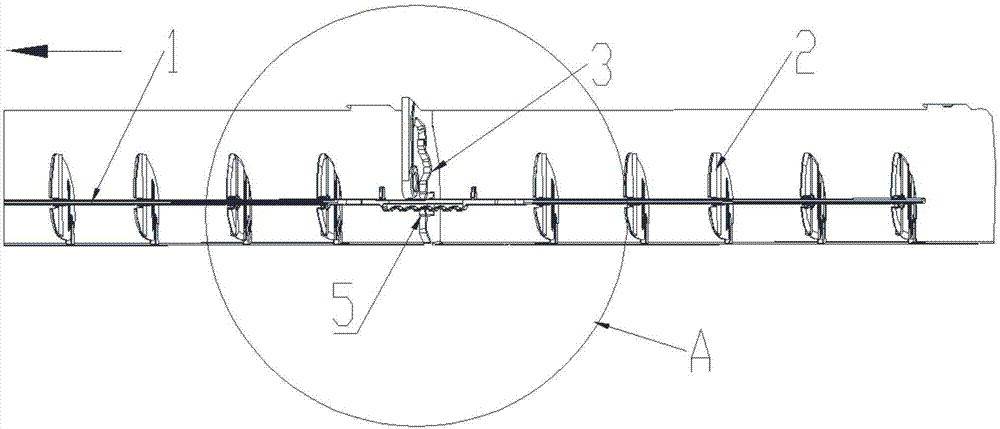
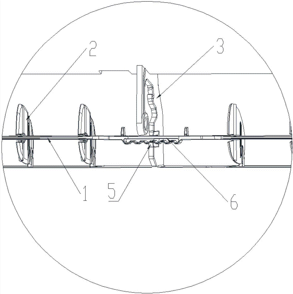
[0047] As the above-mentioned wind guide structure, the difference of this embodiment is that, as figure 2 As shown, there is a buckle 6 on the wind guide connecting rod 1, and the buckle 6 is matched with the slot 5 of the main support frame 3, and the wind guide connecting rod 1 is clamped on the main support on shelf 3.
[0048] Wherein, the buckle 6 has a plurality of snapping positions; in this way, different snapping positions on the buckle 6 can be snapped into the slot 5 respectively, so that the wind guide connecting rod 1 can be snapped on the main support on the frame 3; different clamping positions represent that the relative positions of the air guide link 1 and the main support frame 3 are different, and when the main support frame 3 is fixed at the air outlet, that is, different clamping positions represent The angles of the wind guide vanes 2 are different. In this way, when the angle of the wind guide vanes 2 needs to be adjusted, the wind guide connecting r...
Embodiment 2
[0050] Like the above-mentioned wind guide structure, the difference of this embodiment is that the opening direction of the slot 5 on the main support frame 3 is perpendicular to the buckle 6 (axial direction) on the wind guide connecting rod 1, so that The slot 5 is engaged with the buckle 6; wherein, the two ends of the buckle 6 are elastically connected to the position where the wind guide connecting rod 1 is connected, so that the wind guide connecting rod 1 remains stationary. In some cases, the buckle 6 can move along a direction parallel to the slot 5 , so that the buckle 6 escapes from the slot 5 .
[0051] In this way, under normal circumstances, the buckle 6 is engaged with the slot 5; when the angle of the wind guide vane 2 needs to be adjusted, the buckle 6 is first moved in parallel along the direction of the slot 5 so that the buckle 6 is separated from the slot 5 , at this time, the buckle 6 is no longer engaged with the slot 5, and then the buckle 6 (air guide...
Embodiment 3
[0055]Like the above-mentioned wind guide structure, the difference of this embodiment is that the opening direction of the slot 5 on the main support frame 3 is perpendicular to the buckle 6 (axial direction) on the wind guide connecting rod 1, so that The card slot 5 is engaged with the buckle 6; wherein, the card slot 5 is elastically connected to the buckle 6; when the wind guide connecting rod 1 is moved left or right, the buckle 6 / The locking slot 5 is deformed, so that the buckle 6 and the locking slot 5 are out of the locked state.
[0056] In this way, under normal circumstances, the buckle 6 is engaged with the slot 5; when the angle of the wind guide vane 2 needs to be adjusted, the buckle 6 (wind guide connecting rod 1) is moved left or right, and the slot 5 / The buckle 6 is deformed under the action of an external force (the force to toggle the buckle 6) (the slot 5 is deformed or the buckle 6 is deformed or the slot 5 and the buckle 6 are deformed at the same ti...
PUM
 Abstract
Description
Claims
Application Information
 - R&D Engineer
- R&D Manager
- IP Professional
- Industry Leading Data Capabilities
- Powerful AI technology
- Patent DNA Extraction
Browse by: Latest US Patents, China's latest patents, Technical Efficacy Thesaurus, Application Domain, Technology Topic, Popular Technical Reports.
© 2024 PatSnap. All rights reserved.Legal|Privacy policy|Modern Slavery Act Transparency Statement|Sitemap|About US| Contact US: help@patsnap.com


