A high-temperature cycle removal method for carbon dioxide based on a rotary fixed bed

A technology of carbon dioxide and high-temperature circulation, applied in the direction of direct carbon dioxide emission reduction, chemical instruments and methods, separation methods, etc., can solve the problems of high control difficulty, wear of absorbent particles, complex system, etc., and achieve simple removal process and particle elimination Collision wear, reducing the effect of operation difficulty

Active Publication Date: 2019-05-28
ANHUI UNIVERSITY OF ARCHITECTURE
View PDF6 Cites 0 Cited by
  • Summary
  • Abstract
  • Description
  • Claims
  • Application Information

AI Technical Summary

Problems solved by technology

[0003] The Ohio State University in the United States, the University of Stuttgart in Germany, the Vienna University of Technology in Austria, the Canadian Mineral Energy Research Center, and the Spanish National Coal Institute have all established small-scale CO2 based on calcium-based chemical chains. 2 The capture device provides a lot of useful references for the improvement of this technology. The main problem of the above-mentioned calcium-based chemical chain carbon capture devices is that they all use circulating fluidized beds or bubbling fluidized beds as reactors. The inherent advantages of fluidized beds are The materials are strongly mixed and reacted fully, but at the same time, there are problems such as complex system, high difficulty in control of material fluidization, material separation and transportation, and wear of absorbent particles.

Method used


Image

  • A high-temperature cycle removal method for carbon dioxide based on a rotary fixed bed
  • A high-temperature cycle removal method for carbon dioxide based on a rotary fixed bed
  • A high-temperature cycle removal method for carbon dioxide based on a rotary fixed bed

Examples


Embodiment Construction

[0024] The technical solution of the present invention will be further described below in conjunction with the accompanying drawings.

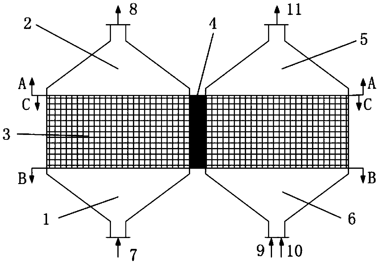
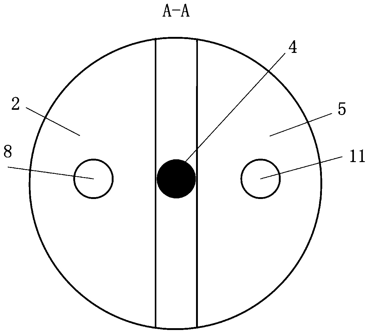
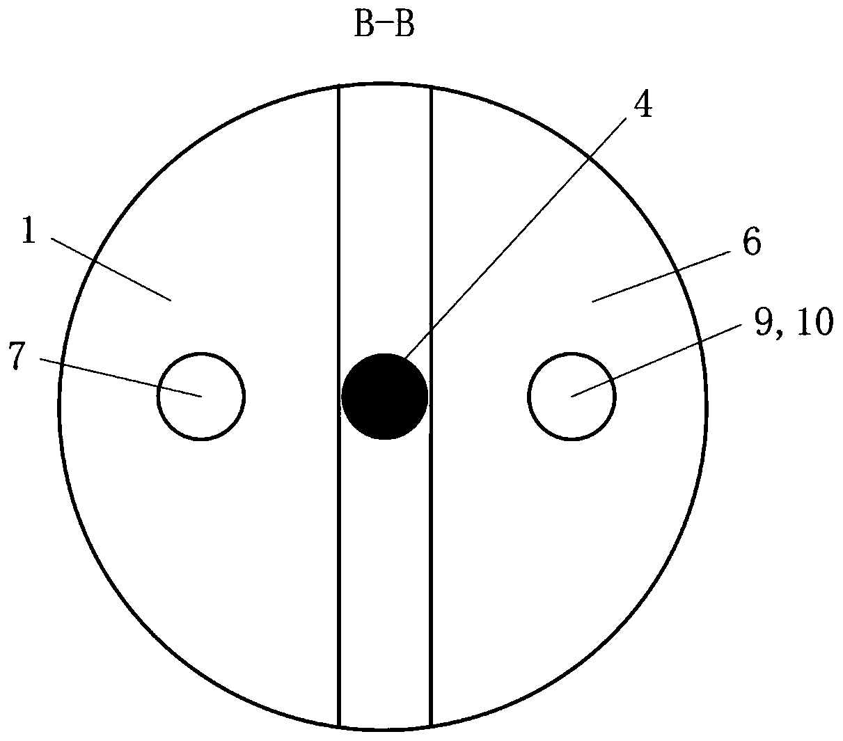
[0025] like figure 1 As shown, the inlet channel 1 on the flue gas side, the outlet channel 2 on the flue gas side, the inlet channel 6 on the fuel gas side, and the outlet channel 5 on the fuel gas side are all fixed, and only the fixed bed rotor 3 rotates periodically.

[0026] The flue gas 7 with a temperature of 500-700°C is sent in from the flue gas side inlet channel 1. When the flue gas 7 flows upward through the fixed bed rotor 3, the CO in the flue gas 7 2 Removed by calcium-based absorbent packing on the flue gas side and forms CaCO 3 , CO removal 2 The rear flue gas 8 is discharged from the flue gas side outlet channel 2. At this time, the CaO in the filler is converted into CaCO through carbonation reaction. 3 ; As the rotor 3 continues to rotate around the rotating shaft 4, the stuffing on the flue gas side rotates to the fuel ...


PUM

PropertyMeasurementUnit
particle diameteraaaaaaaaaa

Abstract

The invention discloses a high-temperature cycle removal method for carbon dioxide based on a rotary fixed bed. The fixed bed rotor filled with calcium-based absorbent rotates to the high-temperature flue gas side channel, and CO2 in the flue gas is removed by the calcium-based absorbent filler and forms CaCO3, after removing CO2, the flue gas is discharged, and CaO is converted into CaCO3 through carbonation reaction; the fixed bed rotor continues to carry the packing that has been converted into CaCO3 to rotate to the fuel gas side channel, and the fuel gas and pure oxygen are passed into this area for combustion and The released heat provides heat for the decomposition of CaCO3, releasing high-concentration CO2, and then CO2 is discharged from the reaction zone and is stored or used for other purposes, and CaCO3 is decomposed and regenerated into CaO; the fixed-bed rotor after the regeneration of the internal filler re-rotates to capture the flue gas The CO2 in the flue gas is separated, and the rotor and the filled absorbent packing are used to periodically pass through the flue gas side and the fuel gas side to complete the CO2 cycle removal and enrichment in the flue gas.

Description

technical field [0001] The present invention relates to CO 2 In the field of emission control and emission reduction, it specifically relates to a high-temperature cycle removal method for carbon dioxide based on a rotary fixed bed. Background technique [0002] Global warming has made countries to reduce CO in the process of fossil energy utilization 2 Emissions are controlled and reduced, currently CO 2 Capture technologies mainly include post-combustion capture (chemical absorption, adsorption, membrane separation, low-temperature fractionation), pre-combustion capture (Linde Rectisol low-temperature methanol washing, UOP Selexol polyethylene glycol dimethyl ether method), oxygen-enriched combustion, etc. Due to the problems of high construction cost and high system efficiency loss in conventional pre-combustion capture, post-combustion capture and oxyfuel combustion technologies, the chemical chain cycle capture of CO based on calcium-based absorbents 2 technology has...

Claims


Application Information

Patent Timeline
Patent Type & Authority Patents(China)
IPC IPC(8): B01D53/62B01D53/82F23J15/02F23J15/06
CPCB01D53/62B01D53/82B01D2251/404B01D2251/602F23J15/02F23J15/06F23J2215/50Y02A50/20Y02C20/40Y02E20/32
Inventor 荣鼐方廷勇朱曙光王晏平马进伟王庚胡浩威马鑫田玺潘玮王杰李文祥
Owner ANHUI UNIVERSITY OF ARCHITECTURE
Why Eureka
Try Eureka