Telescopic spiling with automatic adjusting and centralizing functions

An automatic adjustment and telescopic technology, applied in sheet pile wall, construction, infrastructure engineering and other directions, can solve the problems of increased project cost, low economic benefit, delay in construction period, etc., to save project cost, significant economic benefit and time saving cost effect

Active Publication Date: 2018-05-08
吴健
View PDF6 Cites 0 Cited by
  • Summary
  • Abstract
  • Description
  • Claims
  • Application Information

AI Technical Summary

Problems solved by technology

The general treatment method is to pull out the stressed sheet pile in the reverse direction and then insert the inserted sheet pile, or use a centralizing frame composed of a steel structure platform to improve the piling accuracy. During the construction process of the centralizing frame, several operators need to stand The uprighting work is done manually on the steel structure platform, which has certain potential safety hazards, and both methods will delay the construction period, increase the project cost, and have low economic benefits

Method used


Image

  • Telescopic spiling with automatic adjusting and centralizing functions
  • Telescopic spiling with automatic adjusting and centralizing functions
  • Telescopic spiling with automatic adjusting and centralizing functions

Examples


Embodiment 1

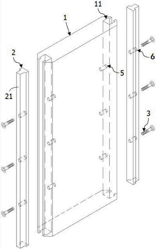
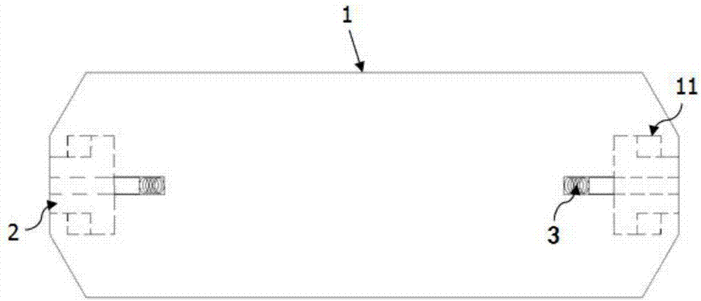
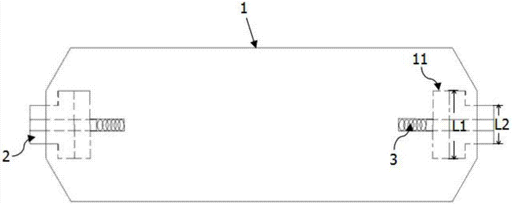
[0022] combine Figure 1 to Figure 3 Shown is a specific embodiment of a retractable sheet pile with automatic adjustment and straightening function of the present invention, which includes a sheet pile body 1 , and telescopic sockets arranged on the left and right sides of the sheet pile body 1 . mechanism. Each telescopic mechanism includes a telescopic plate 2, an elastic member 3 arranged between the telescopic plate 2 and the sheet pile body 1, and the elastic member 3 enables the telescopic plate 2 to move away from the telescopic plate in the left and right direction. Move in the direction of the sheet pile body 1 described above, that is, the telescopic plate 2 is ejected outward relative to the sheet pile body 1 . The length of the expansion plate 2 extends along the longitudinal direction of the sheet pile body 1 , and the length of the expansion plate 2 is equal to the longitudinal height of the sheet pile body 1 . Not shown in the figure, preferably, the lower pa...

Embodiment 2

[0028] Embodiment 2: In this embodiment, combining Figure 4As shown, the difference from Embodiment 1 is that each of the expansion plates 2 is provided with three guide rods 4 extending in the left and right directions, and correspondingly, each of the expansion plates 2 is longitudinally distributed with guide rods 4 for the guide rods. The positions of the second positioning holes 7 where the rods 4 are inserted are projected on the corresponding upper / lower end surfaces of the telescopic plate 2 are misaligned, that is, they are not on a straight longitudinal line. The elastic member 3 is provided between the bottom of each second positioning hole 7 and its corresponding guide rod 4, and in addition, the corresponding guide rod 4 and the second positioning hole 7 are respectively provided with matching limiting bosses. and a tightening part to slidably restrict the guide rod 4 in the second positioning hole (7) in the left and right direction, and each of the second posit...


PUM


Abstract

The invention discloses a telescopic spiling with automatic adjusting and centralizing functions. The telescopic spiling comprises a spiling body and telescopic mechanisms arranged on at least one ofthe left side portion and the right side portion of the spiling body. Each telescopic mechanism comprises a telescopic plate and elastic pieces arranged between the telescopic plate and the spiling body. By means of the elastic pieces, the telescopic plates can move in the direction away from the spiling body in the left-right direction. By means of the telescopic spiling, on one hand, a series ofcomplex operation links for avoiding pile slanting in the pile pulling centralizing operation and pile driving processes can be effectively avoided; and on the other hand, the time cost and the project cost are saved, economic benefits are obvious, and the application range is wide.

Description

technical field [0001] The invention relates to a retractable sheet pile with the function of automatic adjustment and straightening. Background technique [0002] At present, various water conservancy projects and revetment projects require sheet pile cofferdams for retaining water and soil before construction. This sheet pile cofferdam is mainly composed of stressed sheet piles responsible for bearing forces and inserted sheet piles for retaining water and soil , in the prior art, a large-scale pile driver is used for piling construction. Firstly, two stressed sheet piles are driven in sequence, and then inserted sheet piles are driven between two adjacent stressed sheet piles to form a tightly connected Sheet pile cofferdam. However, on the one hand, the huge self-weight of the pile driver itself will aggravate the soil squeezing effect and cause the pile body to tilt. On the other hand, because the pile driving construction is all manual operations, the pile body is not...

Claims


Application Information

Patent Timeline
Patent Type & Authority Applications(China)
IPC IPC(8): E02D19/04E02D5/14E02D5/16
CPCE02D5/14E02D5/16E02D19/04
Inventor 吴健
Owner 吴健
Why Eureka
Try Eureka