Eureka AIR delivers breakthrough ideas for toughest innovation challenges, trusted by R&D personnel around the world.

Grinding mill and ceramic preparation method

A mill and locking mechanism technology, applied in the direction of grain processing, etc., can solve problems such as difficulty in ensuring uniform crushing of materials, uneven viscosity, softness and hardness, and influence on stirring effect, so as to avoid excessive vibration amplitude, save energy, and grind The effect of grinding effect enhancement

Inactive Publication Date: 2018-05-08
江西华硕陶瓷集团有限公司
View PDF10 Cites 2 Cited by
  • Summary
  • Abstract
  • Description
  • Claims
  • Application Information

AI Technical Summary

Problems solved by technology

These materials have the following similarities, such as generally high viscosity, uneven hardness and a large amount of impurities. During the crushing process, due to the certain viscosity of these materials, some of them are relatively viscous during the crushing process in ordinary crushing mills. In addition, soft materials will adhere to the inner wall of the grinding mill rotating cylinder and the grinding balls, forming a cushion of soft mineral materials. It is difficult to ensure that the mate

Method used


Image

  • Grinding mill and ceramic preparation method
  • Grinding mill and ceramic preparation method
  • Grinding mill and ceramic preparation method

Examples


Example Embodiment

[0032] Example 1:

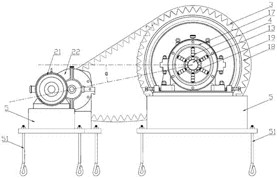
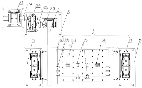
[0033] like Figure 1-2 , a pulverizing mill, including a hollow cylindrical rotating cylinder 1, a motor 21, a base 5 with a ground lock 51 at the bottom, and a material gate 11 on the rotating cylinder 1. The two ends of the material door 11 are flush with each other, and the material door 11 is extended to the outside relative to the rotating drum 1 around the rotating shaft 14. In the closed state, the locking mechanism provided at the corresponding interface between the material door 11 and the rotating drum 1 locks both; in this embodiment , the locking mechanism adopts the locking buckles 15 arranged on the two ends of one side of the rotating shaft 14 and the corresponding interface between the material door 11 and the rotating drum 1, and the locking pair 15 arranged on the side wall 12 of the rotating drum 1 and the material door 11. Locked locking snaps 16 . This design can enhance the bonding strength between the material gate 11 and the wall ...

Example Embodiment

[0041] Embodiment 2:

[0042] like Figure 1-2 , a pulverizing mill, including a hollow cylindrical rotating cylinder 1, a motor 21, a base 5 with a ground lock 51 at the bottom, and a material gate 11 on the rotating cylinder 1. The two ends of the material door 11 are flush with each other, and the material door 11 is extended to the outside relative to the rotating drum 1 around the rotating shaft 14. In the closed state, the locking mechanism provided at the corresponding interface between the material door 11 and the rotating drum 1 locks both; in this embodiment , the locking mechanism adopts the locking buckles 15 arranged on the two ends of one side of the rotating shaft 14 and the corresponding interface between the material door 11 and the rotating drum 1, and the locking pair 15 arranged on the side wall 12 of the rotating drum 1 and the material door 11. Locked locking snaps 16 . This design can enhance the bonding strength between the material gate 11 and the wa...

Example Embodiment

[0047] Embodiment three:

[0048] A method for preparing ceramics using a pulverizing mill, comprising the following processes:

[0049] Weigh the raw materials according to the specific gravity: 5-10 parts of clay, 85-88 parts of quartz, 1-5 parts of CaO and K2O, an appropriate amount of water and an appropriate amount of binder; mix them evenly, place them in a pulverizer and stir for 20-30 After hours, the frequency conversion control system controls the motor to drive the pulverizing mill, and sinters the mixed material after stirring to obtain the ceramic material.


PUM


Abstract

The invention relates to a grinding mill. The grinding mill comprises a cylindrical rotating cylinder, a motor and a base. The grinding mill is characterized in that a material door is formed in the rotating cylinder; the width of the material door is consistent with that of the rotating cylinder; the material door can be overturned outwards relative to the rotating cylinder around a rotating shaft; a locking mechanism is arranged at a corresponding position of the material door and the rotating cylinder; a transmission gear is arranged on the side wall of the rotating cylinder; the motor drives the transmission gear for rotation through a transmission belt; bearings are connected to two sides of the rotating shaft of the rotating cylinder, and are respectively mounted in each bearing mounting ring; a limiting ring and an elastic plate are arranged in each bearing mounting ring; each limiting ring is located in the corresponding bearing mounting ring; a plurality of elastic plates adopt a semi-moon-shaped structure; each limiting ring and the corresponding bearing mounting ring are concentrically arranged; the elastic plates are respectively arranged in an annular region limited byeach limiting ring and the corresponding bearing mounting ring; the arc top of the semi-moon-shaped structure of each elastic plate is in top connection with the outer periphery of the correspondinglimiting ring, and fixation is realized through a corresponding connecting piece; two ends of the semi-moon-shaped structure of each elastic plate are connected with the corresponding bearing mountingring through one corresponding fixing piece; the elastic plates are used for enabling a shaft axis of the rotating shaft to be in reciprocating motion along an elastic mechanism; and the bearing mounting rings are fixed relative to the base, and are supported by the base.

Description

technical field [0001] The invention relates to equipment for ceramic production, in particular to a pulverizing mill and a method for preparing ceramics by using the pulverizing mill. Background technique [0002] In the ceramic production process, it is necessary to crush the mineral materials used to make ceramics into powder before subsequent processing. Common ceramic mineral materials include clay, alumina, kaolin, quartz, feldspar, etc. These materials have the following similarities, such as generally high viscosity, uneven hardness and a large amount of impurities. During the crushing process, due to the certain viscosity of these materials, some of them are relatively viscous during the crushing process in ordinary crushing mills. In addition, soft materials will adhere to the inner wall of the grinding mill rotating cylinder and the grinding balls, forming a cushion of soft mineral materials. It is difficult to ensure that the materials are uniformly crushed durin...

Claims


Application Information

Patent Timeline
IPC IPC(8): B02C17/10B02C17/24B02C17/22B02C25/00C22C38/04C22C38/22C04B35/14
CPCB02C17/10B02C17/22B02C17/24B02C25/00C04B35/14C04B2235/3201C04B2235/3208C04B2235/349C22C38/04C22C38/22
Inventor 王志洪
Owner 江西华硕陶瓷集团有限公司
Why Eureka
Eureka Blog
Learn More