Novel high-lift built-in type submerged pump

A high-lift, submersible pump technology, applied in the direction of non-variable pumps, pumps, pump devices, etc., can solve the problems of high external water pressure of the motor, impeller stuck, gravity eccentricity of the machine barrel, etc., to ensure the performance and guarantee The effect of concentricity

Inactive Publication Date: 2018-05-04
ZHEJIANG FROG PUMP IND
View PDF10 Cites 0 Cited by
  • Summary
  • Abstract
  • Description
  • Claims
  • Application Information

AI Technical Summary

Problems solved by technology

[0002] The submersible pump is an important equipment for lifting water from deep wells. When in use, the entire unit is submerged in the water to work, and then the groundwater is extracted to the surface. When the submersible pump needs to achieve a high lift effect, it is necessary to ensure the number of impellers. Therefore, the higher the number of impellers, the higher the lift. The higher the number, but when the number of impeller stages is high, the water pressure outside the motor will become very high. The mechanical life of ordinary dry motors will drop rapidly due to the large internal and external pressure difference. If the number of impeller stages is made very short , the effective head will become limited, it can only be within 100 meters, and the effect of high head cannot be achieved
[0003] The motor, impeller, guide vane and other components of traditional submersible pumps are all installed in one barrel, so the barrel is generally extremely long. The longer barrel makes it difficult to install the components inside it, which increases the assembly efficiency of the staff , and if the barrel is too long, there will be gravity eccentricity, which will cause side bending at the upper end of the barrel. It is fixed to the lower end of the barrel by screws. This fixing method causes the impeller barrel to be seriously affected by the concentricity between the upper end of the barrel and the lower end of the barrel, resulting in an increase in the probability of the impeller being stuck.

Method used


Image

  • Novel high-lift built-in type submerged pump
  • Novel high-lift built-in type submerged pump
  • Novel high-lift built-in type submerged pump

Examples


Embodiment Construction

[0019] Below in conjunction with accompanying drawing and specific embodiment the present invention will be described in further detail:

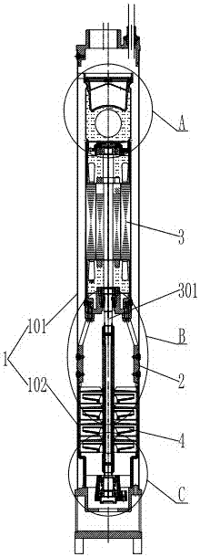
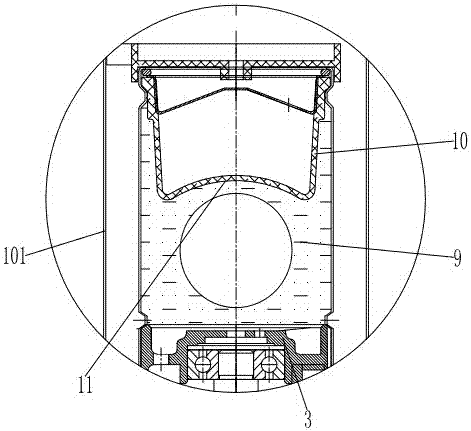
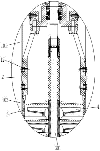
[0020] see Figure 1 to Figure 4 , the present invention provides a new type of high-lift built-in submersible pump, including a barrel 1, the barrel is composed of an upper steel pipe 101 and a lower steel pipe 102, and the upper steel pipe 101 and the lower steel pipe 102 are connected by a connecting pipe 2; A motor 3 is fixed inside the above steel pipe 101; the motor 3 is connected with several stages of impellers 4 through its own motor shaft 301, and the impellers 4 are located in the lower steel pipe 102; the outer casing of the impeller 4 is provided with an impeller barrel 5; A fixing frame 6 is fixed inside the lower end; the adjusting part 7 is installed on the fixing frame 6; the free end of the motor shaft 301 of the motor 3 is connected with the adjusting part 7 through an angular contact ball bearing 8; Mechanical oil 9 is ...


PUM


Abstract

The invention provides a novel high-lift built-in type submerged pump. The novel high-lift built-in type submerged pump comprises a cylinder, wherein the cylinder comprises an upper steel pipe and a lower steel pipe, and the upper steel pipe and the lower steel pipe are connected through a connecting pipe; a motor is fixed in the upper steel pipe and connected with a plurality of impellers througha motor shaft, and the impellers are located in the lower steel pipe; the impellers are sleeved with an impeller cylinder; a fixed bracket is fixed in the lower end of the lower steel pipe; an adjusting part is mounted on the fixed bracket; a free end of the motor shaft of the motor is connected with the adjusting part through an angular contact ball bearing; machine oil is fed into the motor; anoil bag located in the motor is arranged at the top end of the motor and contacted with the machine oil. According to the novel high-lift built-in type submerged pump, inner and outer pressure difference can be balanced while high-lift effect is realized, the mechanical life of each part in the motor is guaranteed, besides, concentricity between the upper end of the cylinder and the lower end ofthe cylinder can be guaranteed, and the condition that the impellers get stuck is prevented.

Description

technical field [0001] The invention relates to a high lift submersible pump. Background technique [0002] The submersible pump is an important equipment for lifting water from deep wells. When in use, the entire unit is submerged in the water to work, and then the groundwater is extracted to the surface. When the submersible pump needs to achieve a high lift effect, it is necessary to ensure the number of impellers. Therefore, the higher the number of impellers, the higher the lift. The higher the number, but when the number of impeller stages is high, the water pressure outside the motor will become very high. The mechanical life of ordinary dry motors will drop rapidly due to the large internal and external pressure difference. If the number of impeller stages is made very short , the effective head will become limited, and it can only be achieved within 100 meters, and the high-lift effect cannot be achieved. [0003] The motor, impeller, guide vane and other component...

Claims


Application Information

Patent Timeline
Patent Type & Authority Applications(China)
IPC IPC(8): F04D13/10F04D29/66F04D29/42F04D29/046
CPCF04D13/10F04D29/0467F04D29/4266F04D29/669
Inventor 金军华
Owner ZHEJIANG FROG PUMP IND
Why Eureka
Try Eureka