Sampling pipe connecting device for coal-mine gas extraction

A coal mine gas and connection device technology, which is applied in the direction of gas discharge, safety devices, mining equipment, etc., can solve problems such as uneconomical, cracks, and drilling air leakage, and achieve the effect of improving the effect, simple structure, and improving the sealing effect

Inactive Publication Date: 2018-05-04
朱元彬
View PDF6 Cites 5 Cited by
  • Summary
  • Abstract
  • Description
  • Claims
  • Application Information

AI Technical Summary

Problems solved by technology

[0002] At present, in the field of coal mines, it is often necessary to drill into coal seams and gas accumulation areas for coal mine gas drainage to prevent safety accidents such as gas explosions and gas outbursts. The borehole is connected to the special pipeline for drainage. To connect the borehole and the special pipeline, the connecting pipe is usually placed in the hole first, and the gap between the connecting pipe and the hole wall is filled with cement slurry or polyurethane, and then the connecting pipe and the hole wall are filled. Special pipes are used for connection. When polyurethane is used to seal holes, polyurethane is prone to foam unevenly, resulting in insufficient sealing, air leakage, poor sealing effect, and high cost of polyurethane, which is not economical. However, the existing cement mortar is used for When sealing holes, the cement mortar is hard and brittle after solidification. When impacted by ground pressure, cracks often occur, causing air leakage in the borehole and affecting the effect of gas drainage. After the drainage is completed, the borehole needs to be sealed. , when using the existing device for plugging, the amount of gas in the hole will gradually increase over time, and the pressure will increase. When the plugging cement mortar becomes loose, it is easy to eject the cement mortar together with the device, causing a safety accident not good

Method used


Image

  • Sampling pipe connecting device for coal-mine gas extraction
  • Sampling pipe connecting device for coal-mine gas extraction

Examples


Embodiment Construction

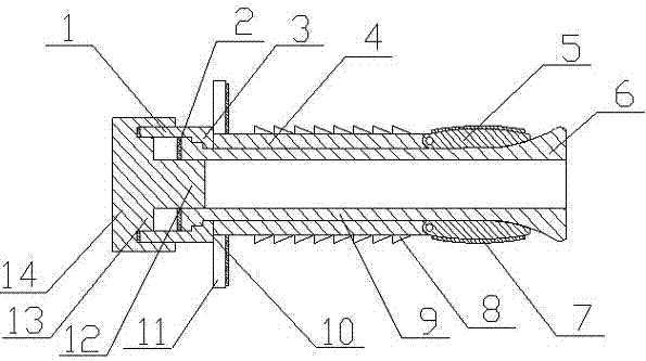
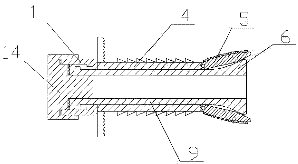
[0022] A coal mine gas extraction sampling pipe connection device of the present invention is realized in this way. When in use, when performing coal mine gas extraction, first put the main rod body (4) into the borehole, and make the stop ring (11) stick At the mouth of the drill hole, then rotate the connecting sleeve (1), because the main snap ring (3) on the connecting sleeve (1) and the auxiliary snap ring (10) on the connecting cylinder (9) are clamped, and then the connecting sleeve (1) ) drives the connecting cylinder (9) to rotate, because the connecting cylinder (9) and the main rod body (4) are screwed together, and then the connecting cylinder (9) moves out of the main rod body (4) during the rotation process, and the connecting cylinder (9) drives The compression block (6) moves into the main rod body (4), and since the diameter of the compression block (6) gradually increases from one end to the other end, the compression block (6) gradually expands the multiple e...


PUM


Abstract

The invention discloses a sampling pipe connecting device for coal-mine gas extraction, and through the coordination of a pressing block and expansion pieces, gaps between a main rod body and a drilling hole wall are sealed. The sealing effect of the gaps between the drilling hole wall and the main rod body can be enhanced effectively, so that no leakage occurs when the gas is extracted, and the extraction effect of gas can be enhanced effectively. The sampling pipe connecting device for the coal-mine gas extraction is characterized in that a limiting ring sleeve is arranged on one end of themain rod body in a sleeving mode, one side of the limiting ring sleeve is provided with a rubber blanket, the outer side of the main rod body is provided with multiple anti-skid latches, the sectionsof the anti-skid latches are right triangles, and the anti-skid latches are made of stainless steel; and one ends of multiple expansion pieces are separately hinged to the other end of the main rod body, the multiple expansion pieces form an annulus, the expansion pieces are made of the stainless steel, the outer sides of the expansion pieces are curved surfaces, and the outer side surface of theexpansion pieces are provided with a no-slip mat.

Description

technical field [0001] The invention relates to a coal mine gas drainage sampling pipe connecting device, which relates to a device for connecting a sampling pipe inserted into a borehole during coal mine gas drainage, and belongs to the field of mining equipment. In particular, it relates to a coal mine gas extraction sampling pipe connection device which seals the gap between the main rod body and the wall of the borehole through the cooperation of the pressing block and the expansion sheet. Background technique [0002] At present, in the field of coal mines, it is often necessary to drill into coal seams and gas accumulation areas for coal mine gas drainage to prevent safety accidents such as gas explosions and gas outbursts. The borehole is connected to the special pipeline for drainage. To connect the borehole and the special pipeline, the connecting pipe is usually placed in the hole first, and the gap between the connecting pipe and the hole wall is filled with cemen...

Claims


Application Information

Patent Timeline
IPC IPC(8): E21F7/00E21B49/08E21B33/12
CPCE21F7/00E21B33/12E21B49/08
Inventor 不公告发明人
Owner 朱元彬
Why Eureka
Try Eureka