Chamfering tool and chamfering machine

A chamfering and tooling technology, applied in the mechanical field, can solve the problems of low wafer control performance, achieve good versatility, simple repair, and increase the pass rate

Pending Publication Date: 2018-05-04
CHANGZHOU C PE PHOTO ELECTRICITY SCI & TECHN
View PDF11 Cites 1 Cited by
  • Summary
  • Abstract
  • Description
  • Claims
  • Application Information

AI Technical Summary

Problems solved by technology

[0005] The object of the present invention is to provide a chamfering tool and chamfering machine, which aims to improve the problem of low wafer control performance of existing chamfering equipment

Method used


Image

  • Chamfering tool and chamfering machine
  • Chamfering tool and chamfering machine
  • Chamfering tool and chamfering machine

Examples


Embodiment

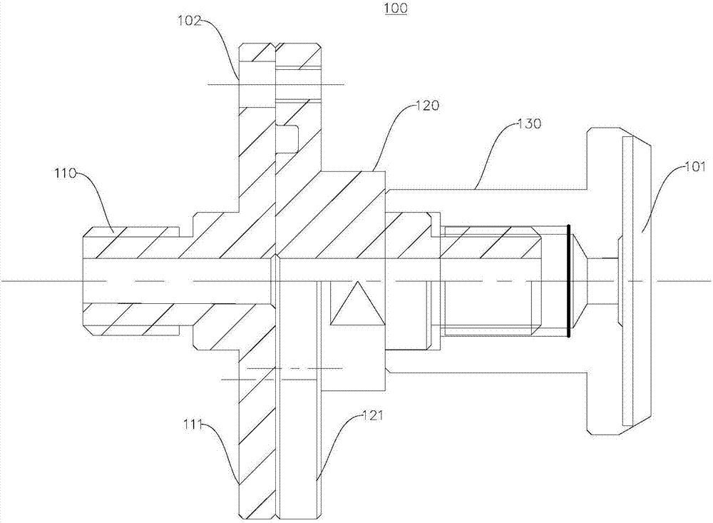
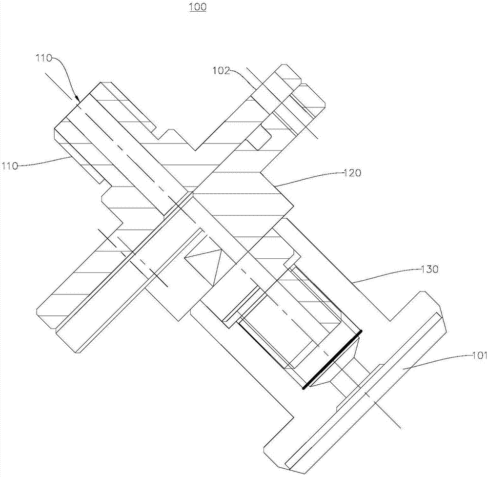
[0038] figure 1 A schematic structural view showing the first state of the chamfering tool 100 provided by the embodiment of the present invention; figure 2 A schematic structural diagram showing the second state of the chamfering tool 100 provided by the embodiment of the present invention; please refer to figure 1 , figure 2 , this embodiment provides a chamfering tool 100, the chamfering tool 100 is mainly used for clamping the wafer 101, and chamfering the wafer 101.

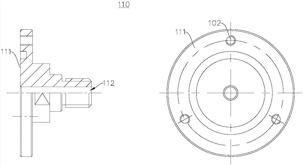
[0039] In detail, in this embodiment, the chamfering tool 100 includes a first joint 110, a second joint 120, and a wafer fixture 130; the first joint 110 is connected to the second joint 120, and the wafer fixture 130 is connected to the second joint 120 . An end of the wafer fixture 130 away from the first joint 110 clamps the wafer 101 .

[0040] Further, the first joint 110 includes a first connecting joint 111; the second joint 120 includes a second connecting joint 121; the second connecting join...


PUM


Abstract

The invention relates to the mechanical field, in particular to a chamfering tool and a chamfering machine. The chamfering tool comprises a first joint, a second joint and a wafer jig. The first jointcomprises a first connecting joint. The second joint comprises a second connecting joint. The second connecting joint and the first connecting joint are connected through adjusting parts, and the positions of the first joint and the second joint can be adjusted by the adjusting parts so that the first joint and the second joint can be coaxial. The wafer jig is connected with the second joint. According to the chamfering tool, millstone repair is simple, and a plane millstone can be adopted for repair; and millstone replacement is not needed, and universality is good. The wafer chamfering efficiency can be improved, and the percent of pass of wafers can be increased. The wafers are precisely located, and the precision can be adjusted to 0.01 mm. The chamfered wafers are consistent and uniform.

Description

technical field [0001] The invention relates to the field of machinery, in particular to a chamfering tool and a chamfering machine. Background technique [0002] The purpose of wafer chamfering is to eliminate the corners, burrs, chipping, cracks or other defects of the wafer and various edge surface contaminations. [0003] In the existing tools for chamfering wafers, the chamfering of wafers is not precise, and the precision is controlled by experience, which requires high technical ability of the operator. [0004] Therefore, the inventor has invented a chamfering tool and a chamfering machine, which can improve the precision of wafer chamfering. Contents of the invention [0005] The object of the present invention is to provide a chamfering tool and a chamfering machine, which aims to improve the problem of low wafer control performance of the existing chamfering equipment. [0006] The invention provides a technical solution: [0007] A chamfering tool, the chamf...

Claims


Application Information

Patent Timeline
Patent Type & Authority Applications(China)
IPC IPC(8): B24B9/06B24B41/04
CPCB24B9/065B24B41/04
Inventor 潘相成陈虹
Owner CHANGZHOU C PE PHOTO ELECTRICITY SCI & TECHN
Why Eureka
Try Eureka