3D printing laser cutting device used for machining inlaying blade line gap of die cutting board

A laser cutting and 3D printing technology, applied in the field of mechanical processing, can solve the problems of affecting cutting quality, tool shaking, poor processing quality, etc., and achieve the effect of improving processing production efficiency, stable connection, and overcoming unstable connection.

Inactive Publication Date: 2018-05-04
HKUST TIANGONG INTELLIGENT EQUIP TECH (TIANJIN) CO LTD
View PDF1 Cites 0 Cited by
  • Summary
  • Abstract
  • Description
  • Claims
  • Application Information

AI Technical Summary

Problems solved by technology

[0002] Die-cutting board is a necessary product in the printing and packaging industry. The gap used for inlaying knives on the die-cutting board is called the knife line. The knife line is very important. The quality and accuracy of the die-cutting work are directly affected by the quality and accuracy of the knife-cutting board. And efficiency, if the knife line is too loose, it may make the knife loose or fall off, or it may cause the knife to shake, which will affect the cutting quality. If the knife line is too tight, it will warp and bulge the die-cutting board, and the light one will affect the quality of die-cutting work In the prior art, for example, the invention patent with the application number 201220624510.2 includes a workbench, which is provided with an electric feed plate capable of reciprocating motion, and a card is installed on the electric feed plate. There is also a bracket fixed o

Method used


Image

  • 3D printing laser cutting device used for machining inlaying blade line gap of die cutting board
  • 3D printing laser cutting device used for machining inlaying blade line gap of die cutting board
  • 3D printing laser cutting device used for machining inlaying blade line gap of die cutting board

Examples


Embodiment Construction

[0020] The following will clearly and completely describe the technical solutions in the embodiments of the present invention with reference to the accompanying drawings in the embodiments of the present invention. Obviously, the described embodiments are only some, not all, embodiments of the present invention. Based on the embodiments of the present invention, all other embodiments obtained by persons of ordinary skill in the art without making creative efforts belong to the protection scope of the present invention.

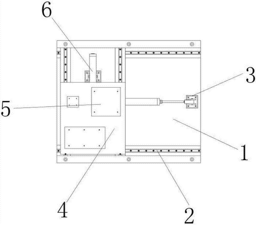
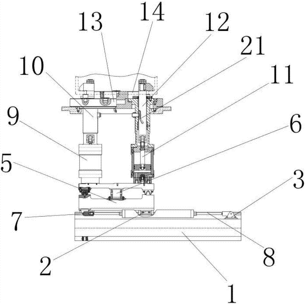
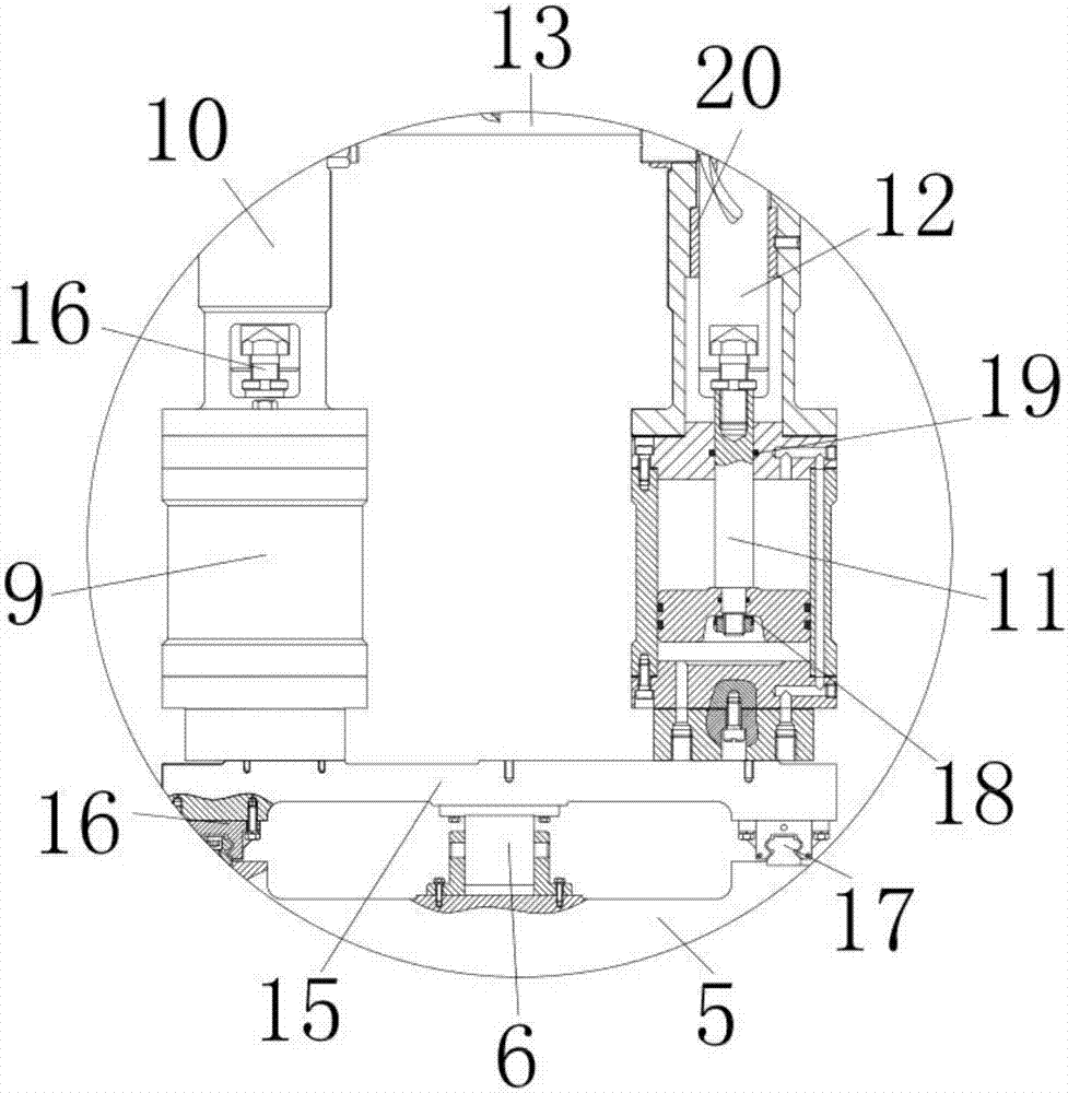
[0021] see Figure 1-4, the present invention provides a technical solution: a 3D printing laser cutting device for processing die-cut board inlaid knife line gaps, including a base 1, the base 1 is made of stainless steel, and is used to install the internal slider 2 and the slider 8, The upper surface of the base 1 is equipped with a fixed corner bracket 3, which is made of stainless steel and is used to fix the slide bar 8. The lower surface of the fixed co...


PUM


Abstract

The invention discloses a 3D printing laser cutting device used for machining an inlaying blade line gap of a die cutting board. A base is included; a fixed corner brace is installed on the upper surface of the base; the lower surface of the fixed corner brace is connected with the upper surface of the base; a sliding rod is installed on the inner wall of the fixed corner brace; the outer wall ofthe sliding rod is connected with the inner wall of the fixed corner brace; a slider is installed on the outer wall of the sliding rod; and the inner wall of the slider is connected with the outer wall of the sliding rod. According to the laser cutting device used for machining the inlaying blade line gap of the die cutting board, due to the cooperation among the base, the fixed corner brace, thesliding rod and a connection rod, and under the effects of a top base, the top base can be driven by the slider to move in the X axis direction on the sliding rod; the defects that a clamp can waggle,a workbench cannot be adjusted in the horizontal direction or the vertical direction, the machining efficiency is low, the machining quality is poor and waste is caused are overcome; and the machining production efficiency is improved, and the 3D printing laser cutting device used for machining the inlaying blade line gap of the die cutting board is applicable to application and popularization.

Description

technical field [0001] The invention relates to the technical field of mechanical processing, in particular to a 3D printing laser cutting device for processing die-cutting board inlaid knife line gaps. Background technique [0002] Die-cutting board is a necessary product in the printing and packaging industry. The gap used for inlaying knives on the die-cutting board is called the knife line. The knife line is very important. The quality and accuracy of the die-cutting work are directly affected by the quality and accuracy of the knife-cutting board. And efficiency, if the knife line is too loose, it may make the knife loose or fall off, or it may cause the knife to shake, which will affect the cutting quality. If the knife line is too tight, it will warp and bulge the die-cutting board, and the light one will affect the quality of die-cutting work In the prior art, for example, the invention patent with the application number 201220624510.2 includes a workbench, which is ...

Claims


Application Information

Patent Timeline
IPC IPC(8): B23K26/38B23K26/08B23K26/70B23K37/04
CPCB23K26/38B23K26/0853B23K26/702B23K37/0435
Inventor 张超钱浩马向军程锦泽吕胜雨王鹏翔
Owner HKUST TIANGONG INTELLIGENT EQUIP TECH (TIANJIN) CO LTD
Why Eureka
Try Eureka